Sample Preparation: Fixation, Staining, and Embedding
Introduction to SBF-SEM Specimen Requirements
The generation of high-quality volumetric image data by Serial Block-Face Scanning Electron Microscopy (SBF-SEM) is fundamentally dependent upon the meticulous preparation of the biological specimen [8, 18, 26]. While the overarching principles of sample processing for SBF-SEM share a common lineage with traditional Transmission Electron Microscopy (TEM)—encompassing fixation, heavy metal staining, dehydration, and resin embedding—the distinct physical and operational demands of the SBF-SEM system necessitate highly specialised and optimised protocols [17, 18, 106, 109] (Figure 15).
In standard TEM, ultrathin sections can be collected on grids and subjected to post-section contrasting with heavy metal salts. In stark contrast, SBF-SEM exclusively relies on imaging the polished block-face of the resin-embedded specimen situated within the high-vacuum chamber of the scanning electron microscope [1, 8, 22, 37, 45]. During an SBF-SEM acquisition cycle, backscattered electrons (BSEs) are collected from the sample surface using low accelerating voltages (typically between 1.5 and 5 kV) to generate an image with an inverted, "TEM-like" contrast [17, 18, 32, 35, 38, 50, 99, 111, 115, 123, 127]. Consequently, all contrast-generating heavy metals must be introduced *en bloc* prior to resin infiltration, and these metals must penetrate deeply and homogeneously throughout tissue volumes that can exceed 1 mm³ [8, 16, 18, 45, 109, 122].
Biological materials are intrinsically composed of light elements (carbon, hydrogen, nitrogen, and oxygen), endowing them with exceptionally low endogenous electron scattering capabilities and poor inherent electrical conductivity [8, 26]. The intense, repeated electron beam irradiation required for SBF-SEM imaging rapidly induces charge accumulation on the surface of non-conductive resin blocks. This charging produces deleterious imaging artefacts—such as image distortion, blurring, drift, and focal plane instability—and compromises the structural integrity of the resin [17, 18, 26, 45, 50, 58]. The repeated *in situ* ultramicrotomy using a diamond knife also demands that the block possesses uniform hardness; weakened or improperly polymerised resin will fragment, chatter, or melt under the beam, destroying the region of interest [17, 18, 24, 26, 45]. Therefore, SBF-SEM sample preparation protocols must carefully balance the preservation of native ultrastructure with massive heavy metal impregnation to maximize BSE yield, optimize electrical conductivity, and render the tissue capable of withstanding both the electron beam and automated microtomy [8, 18, 26].
Primary Chemical Fixation: Arresting Autolysis and Preserving Architecture
The foundational step in the SBF-SEM sample preparation pipeline is chemical fixation, which must be executed immediately upon tissue extraction or *in vivo* to arrest autolysis, halt metabolic processes, and preserve the three-dimensional architecture of the cell [18, 26]. Inappropriate, delayed, or excessively harsh fixation induces cytolysis, cytorrhysis, shrinkage, or the formation of large extracellular voids, severely confounding subsequent morphological analysis [18, 48].
Primary fixation is generally achieved using a combination of aldehydes. Typically, a mixture containing 2–4% paraformaldehyde (PFA) and 1–4% glutaraldehyde (GA) is employed [26, 29, 32, 85, 100, 102, 103, 104, 108, 117, 132, 133]. Glutaraldehyde acts as a highly effective cross-linking agent for proteins, rapidly stabilising the cytoskeleton and the cytoplasmic matrix, while the smaller paraformaldehyde molecule penetrates deeper into large tissue blocks before glutaraldehyde cross-linking is complete [26, 100, 117]. For solid organs such as the brain or liver, transcardial perfusion of the aldehyde fixative is heavily preferred over immersion fixation, as it utilizes the native vasculature to rapidly and uniformly deliver the fixative, thereby minimizing ischaemic damage and ensuring optimal preservation of delicate structures like synapses and microvessels [45, 100, 120, 133].
The aldehydes are universally prepared in a physiological buffer to maintain osmotic balance and pH, most commonly 0.1 to 0.15 M sodium cacodylate or PIPES buffer, buffered to a pH of 7.2 to 7.4 [18, 32, 34, 35, 45, 85, 100, 103, 104, 115, 117, 120, 129]. The osmolarity of the buffer is highly critical; for instance, plant mesophyll cells featuring thin walls and large vacuoles are extraordinarily sensitive to osmotic shock and require meticulous adjustment of the cacodylate buffer concentration to prevent the collapse of organelles [48]. Additionally, calcium chloride (typically 1–4 mM) is frequently added to the primary fixative and washing buffers. Calcium ions play a vital role in stabilising lipid bilayers, preventing the extraction of membrane lipids during prolonged processing, and enhancing the subsequent contrast of the endoplasmic reticulum and other membrane systems [24, 32, 85, 89, 91, 100, 115, 117, 120, 129].
While conventional chemical fixation at room temperature or 4°C is adequate for many robust tissues, certain specimens are prone to extraction artefacts. In such cases, microwave-assisted fixation can be employed to rapidly accelerate cross-linking [52, 107, 125]. For the highest fidelity preservation of tissues in their near-native, fully hydrated state, quick freeze substitution (QFS) or high-pressure freezing (HPF) techniques have been adapted for SBF-SEM [1, 37, 44]. Because the aqueous heavy metal solutions typically used in SBF-SEM are incompatible with sub-zero freeze substitution, modified protocols incorporating heavy metals dissolved in organic solvents (e.g., acetone or methanol) along with contrasting agents like lanthanum chloride or imidazole have been developed to impart sufficient electron density to rapidly frozen specimens [1, 44].
Post-Fixation and the Principles of Mega-Metal Impregnation
Following aldehyde cross-linking and exhaustive buffer washes, the tissue undergoes extensive post-fixation and contrasting, colloquially termed "mega-metal" protocols [8]. Because standard TEM osmium staining does not yield sufficient BSE signal for the low accelerating voltages (2–5 kV) used in SBF-SEM, protocols have evolved to artificially inflate the concentration of heavy metals bound to the tissue [1, 8, 18].
Osmium tetroxide (OsO₄) serves as the primary post-fixative and electron stain. OsO₄ preferentially reacts with unsaturated acyl chains of membrane lipids, cross-linking them and rendering them insoluble during subsequent dehydration steps, while simultaneously depositing electron-dense osmium atoms [8, 26, 34, 99]. However, to dramatically amplify membrane contrast and reduce the "coring effect" (where lipid droplets and membranes stain intensely only at their periphery), modern SBF-SEM protocols almost exclusively utilize a reduced osmium protocol (often abbreviated as rOTO) [9, 16, 18, 34, 77, 102, 120, 122].
In the reduced osmium step, tissues are incubated in a freshly prepared mixture of 2% aqueous OsO₄ and 1.5–3% potassium ferrocyanide (K₄[Fe(CN)₆]) [9, 18, 32, 35, 38, 45, 85, 89, 91, 100, 101, 102, 103, 104, 111, 112, 114, 115, 117, 120, 132, 134, 135]. The potassium ferrocyanide acts as a reducing agent, converting the volatile Os(VIII) to lower oxidation states (e.g., Os(VI) or Os(IV)), which precipitate more readily and stably on lipid bilayers, substantially increasing membrane electron density [132]. For plant tissues, where potassium ferrocyanide tends to heavily stain cell walls and obscure intracellular structures like plasmodesmata, substituting potassium ferrocyanide with potassium ferricyanide (K₃[Fe(CN)₆]) has been shown to successfully restrict heavy metal deposition to the membranes, facilitating superior automated segmentation [35, 48, 99].
Signal Amplification via Bridging Agents: TCH, Tannic Acid, and Pyrogallol
Following the initial reduced osmium incubation and thorough washing in ultrapure water, signal amplification is achieved by introducing a molecular bridging agent—a mordant—that binds to the previously deposited osmium and provides free reactive sites for subsequent, secondary osmium binding. This cascading deposition of heavy metals dramatically enhances both image contrast and the bulk electrical conductivity of the block [18, 26, 45, 99].
The most universally applied bridging agent is thiocarbohydrazide (TCH), forming the core of the OTO (osmium-thiocarbohydrazide-osmium) and rOTO (reduced OTO) methods originally pioneered by Seligman and refined by Deerinck and Ellisman at the National Center for Microscopy and Imaging Research (NCMIR) [9, 16, 18, 26, 32, 34, 38, 45, 77, 85, 89, 91, 102, 107, 110, 111, 112, 114, 115, 117, 120, 124, 132, 134]. TCH (typically 1% w/v) is incubated with the tissue, thoroughly washed, and then the tissue is exposed to a second round of 2% aqueous OsO₄. This secondary osmication binds to the TCH framework, compounding the metal density along lipid membranes [9, 18, 26, 32, 38, 45, 85, 89, 91, 102, 111, 112, 115, 117, 120, 124, 134].
While TCH is highly effective for membrane contrast, alternative mordants are utilised depending on the tissue and target structures. Tannic acid (0.1–1% w/v) is frequently employed either alongside or in place of TCH to drastically increase the electron density of proteins, particularly extracellular matrix components like collagen and elastin, while also staining the cytoplasm more uniformly [1, 9, 18, 34, 58, 77, 99, 103, 104, 105, 109, 116, 135]. However, tannic acid penetrates tissues slowly, necessitating extended incubation times for blocks exceeding 1 mm³ [116].
A significant limitation of TCH in very large tissues (such as whole mammalian brains) is the generation of nitrogen gas bubbles during the chemical reaction, which can induce severe mechanical disruptions, cracks, and microscopic voids within the neuropil [16, 128]. To combat this, pyrogallol has been introduced as a substitute bridging agent in the ROPO (reduced osmium-pyrogallol-osmium) and BROPA (Brain ROTO with Pyrogallol and Formamide) protocols [9, 16, 45, 122, 128]. Pyrogallol acts identically to TCH in bridging osmium molecules but does not liberate nitrogen, thereby preserving the structural integrity of massive tissue blocks while enabling uniform staining depths previously unattainable [16, 45, 122, 128]. For rapid sample turnover, the "fast BROPA" (fBROPA) protocol modifies reaction temperatures and concentrations to achieve dense whole-brain staining in a fraction of the time [109, 122].
Broad-Spectrum En Bloc Staining: Uranium, Lead, and Non-Radioactive Alternatives
To complement the lipid-centric contrast provided by osmium, SBF-SEM samples are universally treated with additional heavy metal salts that target nucleic acids, proteins, and the cytoplasm, yielding a holistic and highly conductive tissue block.
Uranyl acetate (UA) is a standard en bloc contrast agent that preferentially binds to chromatin, ribosomes, and cytoskeletal elements [9, 18, 26, 32, 45, 85, 89, 102]. Tissues are typically incubated in 1–2% aqueous UA overnight at 4°C, or accelerated by heating to 40–50°C [32, 38, 45, 85, 91, 102, 103, 111, 112, 113, 114, 115, 117, 120, 124, 125, 126, 129, 132, 133, 134, 135]. In some neural tissue protocols (such as Large Volume Block Staining, LVBS), uranyl acetate dissolved in ethanol (UA-EtOH) is used to selectively reduce cytoplasmic staining whilst maintaining intense electron density at the post-synaptic densities (PSDs), facilitating the reliable identification of asymmetric excitatory synapses during 3D reconstruction [77].
Following uranyl acetate, Walton’s lead aspartate staining is broadly applied to further enhance the overall signal-to-noise ratio [9, 18, 26, 32, 38, 45, 58, 85, 91, 102, 103, 107, 111, 112, 113, 114, 115, 117, 120, 124, 125, 126, 129, 134]. Formulated by dissolving lead nitrate in aspartic acid and carefully adjusting the pH to 5.5, the solution is applied to the tissue at 60°C for 30 to 120 minutes [32, 38, 45, 85, 91, 102, 103, 111, 112, 113, 114, 115, 117, 120, 124, 125, 134]. The elevated temperature and specific pH are essential to drive the precipitation of lead onto the pre-existing uranium and osmium complexes, heavily contrasting the intracellular architecture and further fortifying the block's electrical conductivity.
Despite its efficacy, the use of uranyl acetate is increasingly restricted globally due to its chemical toxicity, radioactivity, and the associated bureaucratic burdens of radioactive waste disposal [9, 26, 45]. Consequently, several non-radioactive lanthanide salts—including samarium triacetate, gadolinium triacetate, and neodymium acetate (e.g., UA-Zero)—have been successfully validated as potent replacements for en bloc SBF-SEM staining [9, 26, 45, 58, 105]. Lanthanide protocols—particularly when the preceding osmication steps are performed at elevated temperatures (e.g., 50°C)—have demonstrated equivalent, and occasionally superior, contrast compared to classical ROTO methods, clearly resolving delicate structures such as nuclear pores, mitochondrial cristae, and synaptic vesicles whilst markedly reducing sample charging under high vacuum [45] (Figure 16).
For certain historical archival materials or specific investigations into plant endomembrane systems, alternative compounds like zinc iodide-osmium (ZIO) have been effectively utilised to impart sufficient BSE contrast for SBF-SEM without relying on the extended multi-day rOTO pipeline [18, 37].
Dehydration and Resin Infiltration
Once all heavy metal impregnation is complete, the tissue must be thoroughly dehydrated before it can be infiltrated with a hydrophobic epoxy resin. Due to the massive quantities of unreacted heavy metal salts present, intermediate wash steps with double-distilled water must be exceptionally rigorous (often 5 x 3 minutes or more) between every single contrasting stage to prevent catastrophic off-target precipitation of osmium, uranium, or lead within the extracellular spaces [32, 38, 45, 91, 103, 107, 111, 112, 113, 114, 115, 117, 120, 125, 134]. The use of automated tissue processors is highly recommended to ensure uniform agitation and to drastically reduce the arduous manual labour and exposure to toxic reagents associated with these prolonged protocols [91, 106, 107, 120].
Dehydration is typically achieved by passing the sample through a graded series of organic solvents, such as ethanol (e.g., 20%, 50%, 70%, 90%, 100%) or acetone, often concluding in anhydrous acetone or propylene oxide [26, 32, 48, 85, 91, 99, 100, 102, 103, 111, 112, 114, 115, 117, 120, 124, 125, 126, 129, 132, 134, 136]. Acetone is a highly effective solvent that mixes seamlessly with epoxy resins, facilitating rapid infiltration; however, it rapidly dissolves certain laboratory plastics, rendering it unsuitable for the *en face* embedding of cultured cells grown on plastic tissue culture dishes [99]. In such cases, ethanol is strictly employed [99].
The transition into resin occurs incrementally, typically starting with a 1:3 ratio of resin to solvent, followed by 1:1, 3:1, and multiple exchanges of 100% fresh resin, often facilitated by vacuum cycling or gentle rotation over several days to ensure complete penetration into the dense, metal-hardened tissue [91, 103, 114, 115, 117, 120, 121, 124, 125, 126, 129, 132, 134, 136].
Resin Embedding: Matrix Hardness and Beam Stability
The physical properties of the embedding resin are of paramount importance in SBF-SEM. The ideal resin must effortlessly infiltrate the specimen, but more critically, it must withstand prolonged irradiation from the electron beam without melting, sublimating, or shrinking, while simultaneously permitting the reliable and smooth sectioning of ultrathin slices (typically 20–100 nm) by a diamond knife inside a high-vacuum chamber [8, 18, 26, 38]. Resins conventionally used for TEM sectioning are often too soft or insufficiently cross-linked for SBF-SEM, leading to "skip-and-cut" artefacts (where the knife compresses rather than slices the block) or gross topographical distortions [26, 38, 45].
Durcupan ACM is arguably the most extensively validated and widely adopted resin in the SBF-SEM literature [8, 17, 18, 26, 38, 48, 85, 87, 99, 100, 102, 111, 114, 115, 119, 121, 124, 127, 129, 131, 132, 136]. Its heavily cross-linked epoxy formulation grants it extraordinary stability under high electron doses, minimising Z-axis shrinkage [8, 38]. However, Durcupan exhibits a markedly high viscosity, necessitating extended infiltration times, especially for densely packed tissues [8]. Epon and EMbed-812 (formulated to a "hard" grade) are similarly robust epoxy resins that perform exceptionally well in SBF-SEM [8, 26, 99, 126, 127, 134].
For tissues shielded by impermeable barriers—such as the rigid cellulose cell walls of plant and fungal tissues—low-viscosity resins are often mandatory to prevent incomplete infiltration [8]. Spurr's low-viscosity resin is historically unparalleled for infiltrating plant material [8, 18, 26, 38, 48, 52, 57, 87, 99]. Nevertheless, Spurr's resin is highly susceptible to severe charging artefacts under the electron beam, manifesting as extreme bright or dark distortions that completely obscure biological features [8]. Agar Low Viscosity (ALV) resin has recently emerged as an effective, less toxic alternative to Spurr's resin that better maintains dimensional integrity during SBF-SEM microtomy [18]. Conversely, while acrylic resins like LR White demonstrate remarkably low charging profiles and are easy to handle, their overall imaging contrast and strict polymerisation requirements (oxygen exclusion and UV cross-linking) render them less optimal for routine SBF-SEM [8, 26]. Once fully infiltrated, the epoxy resins are typically polymerised in an oven at 60–70°C for 48 to 72 hours to ensure a uniform, hard block [28, 85, 87, 91, 103, 115, 120, 121, 123, 124, 125, 126, 129, 132, 134, 136].
Charge Mitigation Strategies: Sample Mounting and Conductive Additives
Because epoxy resins are electrical insulators, electrons from the primary beam that are not backscattered or absorbed by the heavy metals rapidly accumulate on the block surface. In SBF-SEM, where the block cannot be re-coated with carbon or gold between every successive slice, this charging is a persistent hazard [8, 17, 18, 26, 38, 45, 50, 58, 119].
To physically ground the specimen, the polymerised resin block is carefully extracted and mechanically trimmed—using razor blades or a glass knife—into a small truncated pyramid or tower, ideally featuring a block-face no larger than 0.5 mm × 0.5 mm [18, 26, 28, 39, 50, 85, 99, 115, 132]. This trimming step is absolutely critical: any excess "blank" resin lacking heavy metal-stained tissue will instantly charge, deflecting the beam and causing focus drift [26, 28]. The trimmed block is subsequently mounted onto an aluminium specimen pin or rivet using a highly conductive silver-based epoxy glue (e.g., CircuitWorks CW2400) [18, 28, 29, 39, 50, 52, 85, 99, 102, 107, 115, 121, 124, 129, 130, 132, 134]. Care is taken to physically connect the exposed heavy-metal-rich tissue at the base of the block directly to the silver epoxy, providing a continuous grounding path for the electrons [28, 99]. Finally, the entire assembled pin—excluding the very top block-face, or occasionally including it if an initial 'clearing' cut will be made by the microtome—is sputter-coated with a thin (5–20 nm) continuous layer of gold, platinum, or palladium to construct a Faraday cage around the specimen [18, 28, 32, 35, 39, 50, 52, 102, 115, 121, 123, 124, 130, 132, 134].
In extreme cases where the tissue itself lacks sufficient heavy metal uptake (e.g., highly vacuolated plant cells, large expanses of unstained extracellular matrix, or lung alveoli), conductive resins can be employed [34, 45, 119]. These formulations integrate conductive fillers, such as Ketjen black (a carbon black powder), carbon nanotubes, or finely dispersed silver particles directly into the liquid epoxy [8, 18, 26, 34, 38, 119]. While highly effective at quenching charging and improving achievable resolution, the addition of macroscopic carbon makes the resin block completely opaque black. This heavily impedes light microscopic targeting of the region of interest (ROI) and, if poorly dispersed, carbon agglomerates can rapidly degrade the diamond knife edge during sectioning [8, 18, 26]. Alternatively, "Minimal Resin" (MR) embedding protocols have been developed. These procedures utilise ultrathin layers of resin or remove bulk resin entirely during polymerisation to reduce the insulating volume surrounding the tissue, markedly reducing charging artefacts without compromising the microtome knife [29, 58, 105]. In instruments equipped with variable pressure capabilities or focal charge compensation (FCC), introducing a small amount of nitrogen gas or water vapour into the chamber can also neutralise surface charge, albeit occasionally at the cost of the ultimate signal-to-noise ratio [17, 26, 35, 52, 58, 118, 121, 130, 136].
Special Considerations for Cell Cultures and CLEM Workflows
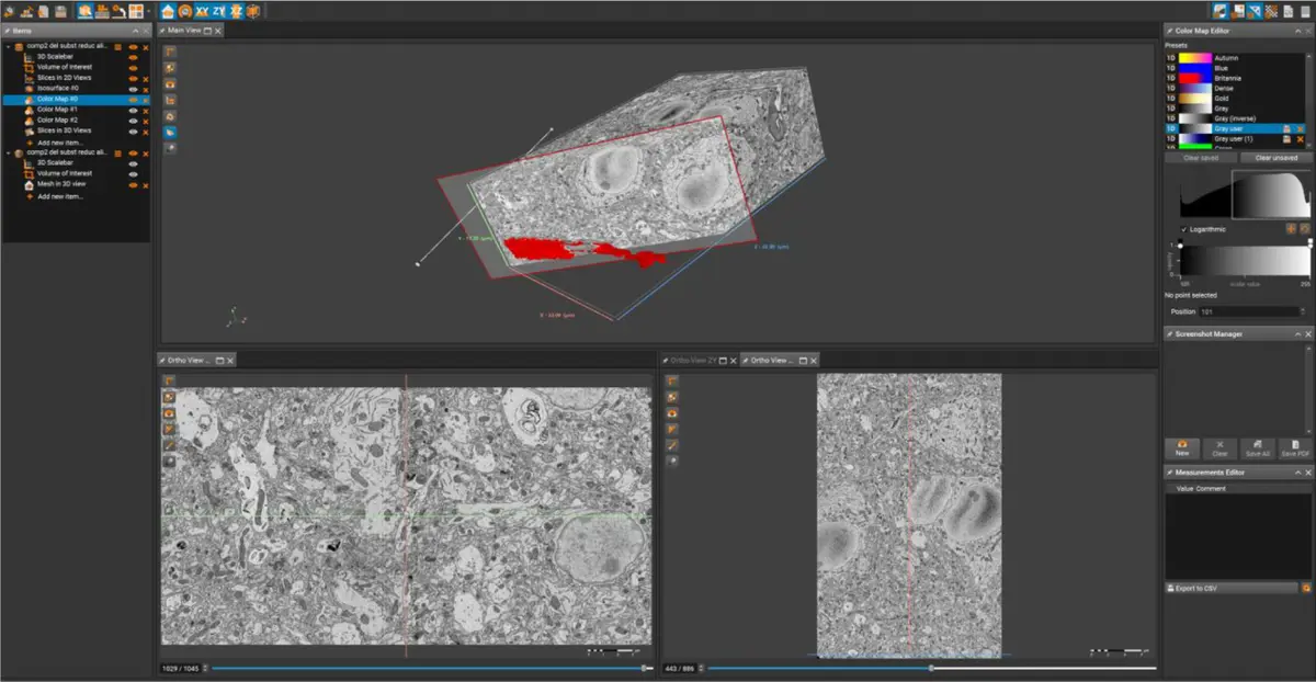
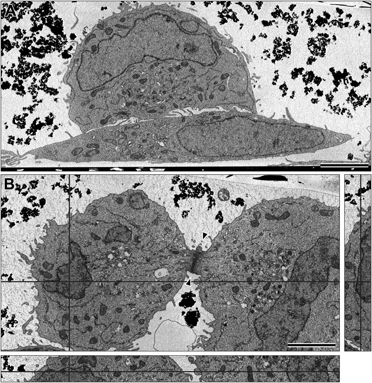
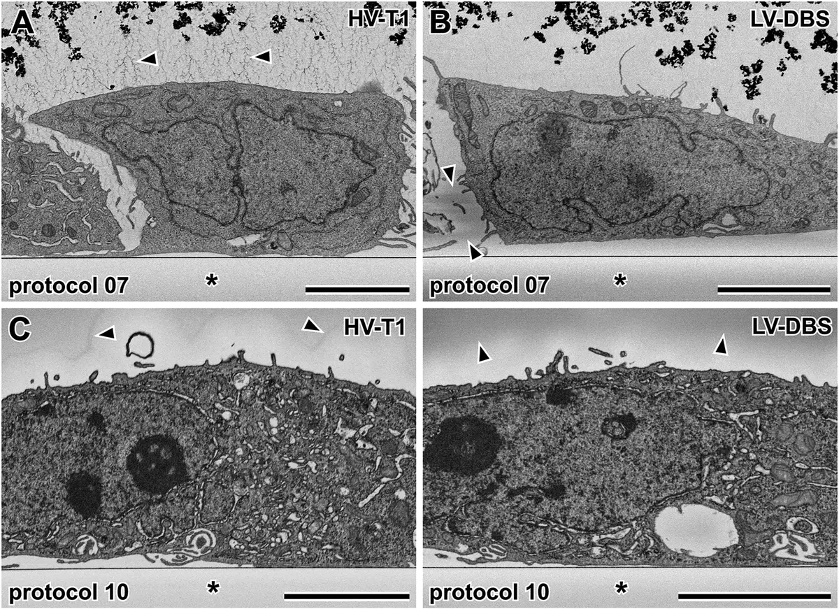
While volumetric analysis historically targeted bulk tissues, the SBF-SEM methodology has been comprehensively adapted for *in vitro* mammalian cell culture monolayers [26, 58, 99, 101, 105, 110]. For suspended cells, standard pelleting techniques are utilised [26, 99, 101, 117]. However, for adherent cells, removing them from their substrate destroys essential spatial contextual data and cell-matrix interactions [58, 99, 105]. Consequently, cells are often grown on specialised gridded coverslips, Aclar film, or thin-bottomed plastic dishes, allowing them to be fixed, heavily osmicated, and embedded *en face* directly onto the substrate [26, 58, 99, 101, 104, 105] (Figure 17).
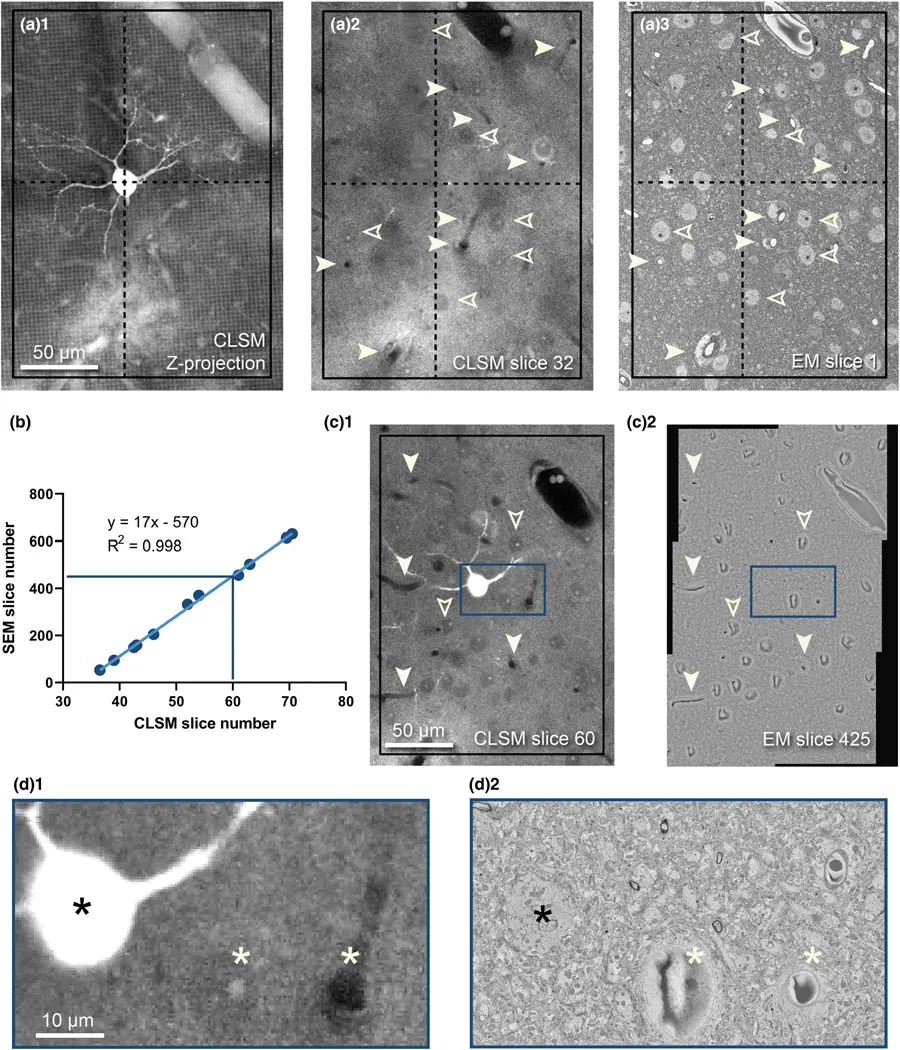
This *en face* methodology is particularly powerful when integrated with Correlative Light and Electron Microscopy (CLEM) workflows. CLEM enables investigators to locate rare or highly specific biological events using fluorescently labelled markers under a light microscope, and subsequently target that exact cell for ultra-high-resolution SBF-SEM 3D reconstruction [8, 26, 99, 101, 124].
However, CLEM imposes severe paradoxical constraints on SBF-SEM sample preparation. The intense mega-metal protocols required for backscattered electron contrast—particularly osmium tetroxide—violently quench fluorescence and destroy endogenous fluorophores (like GFP) and exogenous dyes [8]. Standard practice involves imaging the cells using fluorescence or confocal microscopy *prior* to heavy metal application [99, 103, 104, 124]. To facilitate the relocation of the cell of interest in the opaque, black resin block post-staining, techniques such as near-infrared branding (NIRB) can be used to burn permanent fiducial reference marks into the substrate around the ROI, which are easily visible during microtome trimming [50] (Figure 18).
Recent material innovations aim to bridge this gap. The introduction of specialised acrylic resins, such as R221, which polymerise via UV cross-linking at low temperatures, has shown immense promise [8]. These resins help preserve in-resin fluorescence while concurrently mitigating electron accumulation on the block surface, representing a crucial frontier in making correlative high-throughput SBF-SEM seamless [8]. Regardless of the embedding approach, successful SBF-SEM relies on an intricately tuned balance of chemical fixation, targeted mega-metal contrast, precise dehydration, and structurally resilient, conductive embedding to yield unparalleled three-dimensional insights into cellular ultrastructure.