SAMURAI 3 User Manual
Everything you need to install the Katana microtome, collect images with Samurai 3, and analyse them in Studio.
Choose a topic below to get started. You can also search the whole manual from the contents list. Each chapter tells you what to click and what happens next, with pictures of the real screens. This edition is for Samurai 3.1 (25 September 2026).
Find your way
How this manual is written
| You see | It means |
|---|---|
| Generate Cycles | A label exactly as it appears in Samurai. It can be a button, a field, a menu item or a panel title. |
| Settings › Advanced › ROI Lock Priority | A path. Open Settings, go to the Advanced section and find ROI Lock Priority. |
| The same icons you see on the buttons in Samurai. | |
| Ctrl/⌘+Z | Press the keys together. Use Ctrl on Windows and ⌘ (Command) on macOS. |
| Numbered red dots on a screenshot | The list under the picture explains each number. |
The numbers in the screenshots (pixel sizes, positions, dates) are only examples, not recommended settings. The drawings show how things work. They are not to scale. Click any picture to see it larger.
The manual is in English, 日本語, 中文, Français and Português. Use the language buttons at the top of the page to switch. The manual works without an internet connection. Press / to search.
System overview
The Katana is a serial block-face microtome. It fits inside the vacuum chamber of a scanning electron microscope (SEM). A PC with the Samurai 3 software controls the microtome and the microscope together, so the two work as one instrument. Together, they image the surface of a resin-embedded sample, cut a thin section away, image the new surface, and repeat. This can go on for hours or weeks without anyone touching it.
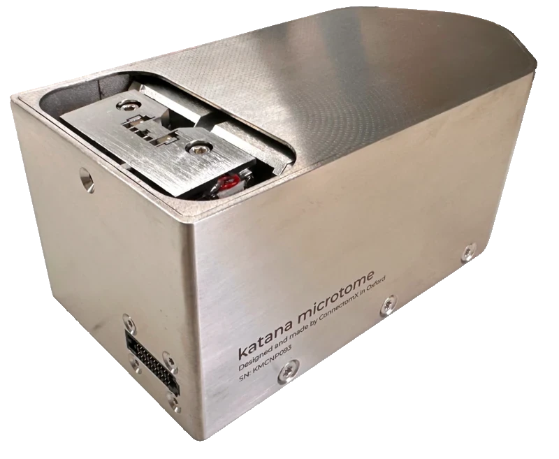 Microtome
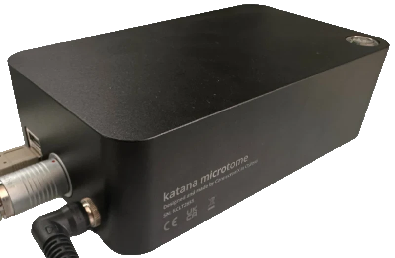 Electronics controller
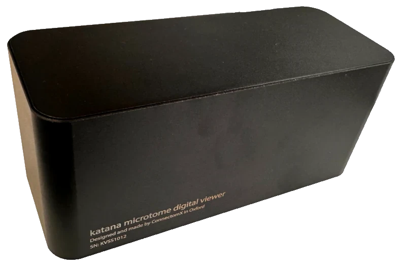 Digital Viewer
1.1 How serial block-face imaging works
Serial block-face scanning electron microscopy (SBF-SEM) builds a 3D picture of a sample, one layer at a time. Each repetition is called a cycle:
- Image. The SEM scans the exposed top surface of the sample, called the block face. It records one image per tile.
- Cut. The diamond knife sweeps across the block face and removes a thin section. A section is usually 20–100 nm thick.
- Raise. The microtome raises the sample by one section thickness. The new block face then sits exactly in the same cutting plane, the height where the knife cuts.
The images are stacked in cutting order. Together they form a 3D volume.
1.2 The hardware
Microtome. The unit inside the chamber. It holds the sample on a sample pin and raises it with a precision Z stage. It cuts with a diamond knife that oscillates (vibrates back and forth). The microtome sits on a stage adapter on the SEM stage. It connects to the outside through the chamber flange, a sealed connector plate in the chamber wall.
Electronics controller. The box outside the microscope. It powers the microtome and drives its motors and knife oscillator. It talks to the Samurai PC over USB.
Digital Viewer. A removable optical camera. It sits on the microtome while you bring a new sample to the knife. This step is called the approach (Chapter 9, The approach). You remove the camera before you close the chamber.
Samurai can also control optional equipment:
- PCN needle — a motorised needle with its own controller. It sits close to the imaged area to reduce charging (a build-up of electrons that spoils the image). See Chapter 20, The PCN needle.
- EDS detector — Oxford Instruments AZtec. It makes elemental maps of the tiles you choose. See Chapter 22, EDS maps with Oxford AZtec.
1.3 The software
Samurai 3 runs on the host PC. It has three workspaces. You choose one with the tabs at the top of the window:
| Workspace | What you do there |
|---|---|
| Approach | Bring a new block face to the knife while you watch it through the Digital Viewer. |
| Imaging | Plan and run experiments. This covers regions of interest, tiles, cycles, automatic focus, quality checks and live monitoring. |
| Studio | Analyse images: processing, registration, segmentation, 3D rendering, measurement and export. Registration lines images up, and segmentation marks out structures. Studio is an optional module. |
Samurai does not talk to the microscope directly. A small companion program sits in between: the Universal SEM Bridge. It runs on the microscope PC or on a PC next to it. It speaks the microscope maker's own interface. Samurai gets one connection that works the same way, whatever the brand. To connect, see Chapter 7, Connecting your equipment.
1.4 Words you will meet everywhere
| Term | Meaning |
|---|---|
| Block face | The exposed top surface of the sample. The SEM images it in each cycle. |
| Cutting plane | The height at which the knife cuts. The microtome brings the block face to this height for every cut. |
| Cycle | One repetition of image → cut → raise. Cycle numbers start at 1. |
| Experiment | Everything about one run: its settings, regions, cycles and images. |
| ROI | Region of interest. An area you choose to image, filled with a grid of tiles. |
| Tile | One SEM image at one position inside an ROI. |
| Time Travel | Viewing and planning any cycle: past, present or future. |
The full list is in Chapter 38, Glossary.
The microtome and its controller
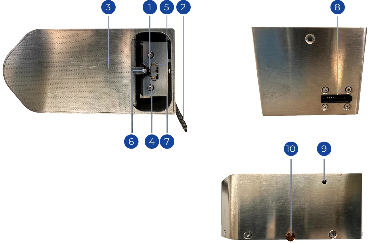
2.1 Parts of the microtome
The microtome is the part that goes into the SEM chamber. It holds the sample on a pin and raises it with a precision stage. It cuts the sample with a diamond knife that oscillates (vibrates back and forth).
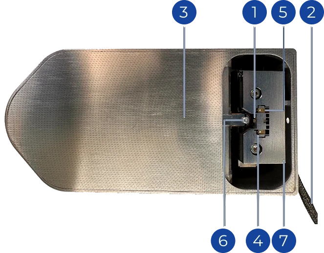 Top
Top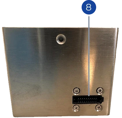 Side
Side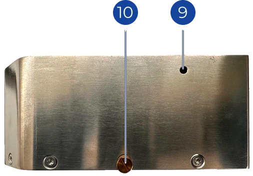 Bottom
| # | Part | What it does |
|---|---|---|
| 1 | Diamond knife | The cutting edge. Keep it clean, and keep it covered whenever you are not cutting. |
| 2 | In-chamber cable | Connects the microtome to the controller through the chamber flange (a sealed connector plate in the chamber wall). |
| 3 | Sample navigation arrows | Show the cutting direction. They help you orient the sample. |
| 4 | Driving oscillator | Vibrates the knife at a set frequency for cleaner cuts. |
| 5 | Sensing oscillator | Measures the vibration so that it can be controlled. |
| 6 | Sample pin | Holds the mounted sample. It sits in the stage. |
| 7 | Knife holder | Clamps the knife and makes its electrical connection. |
| 8 | Main connector | Where the in-chamber cable (2) plugs in. |
| 9 | Pin clamp access hole | Put the screwdriver in here to clamp or release the sample pin. |
| 10 | Stage thumb screw | Fixes the microtome to the stage adapter. |
2.2 The electronics controller
The controller sits outside the microscope. It powers the microtome and drives its motors and knife oscillator. It also connects to the Samurai PC.
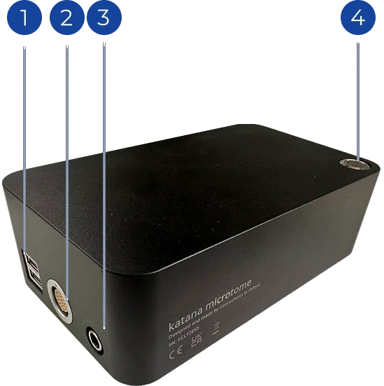
- USB ports — connect the Samurai PC here. You can also connect other instruments, if your setup needs them.
- Main connector — connects to the chamber feedthrough flange. Inside the chamber, the in-chamber cable runs from the flange to the microtome's main connector.
- 48 V input — for the supplied 48 V power supply only.
- Main switch — turns the power on and off.
2.3 The Digital Viewer
The Digital Viewer is an optical camera. It clips onto the microtome while the chamber is open. With it, you watch the knife and the block face during the approach, while you bring them together (Chapter 9, The approach). Its picture appears in the Approach tab.
Installation
The microtome sits inside the SEM's vacuum chamber. So installing it is mostly about two things: keeping everything clean, and making sure nothing in the chamber can hit it.
3.1 Keep everything clean
The microtome must be free of contamination. So must every part that goes into the vacuum: the flange, the stage adapter and the in-chamber cable. The flange is the sealed connector plate in the chamber wall. If these parts are not clean, the microscope's vacuum and image quality suffer.
- Wear fresh gloves whenever you handle the microtome or its accessories.
- If you see contamination, wipe it gently with a lint-free tissue moistened with isopropanol.
- Let every surface dry completely, with no residue, before it goes into the chamber.
3.2 Make room in the chamber
The microtome is large compared with most sample holders. Before you install it:
- Remove detectors you will not use. Retract the detectors that stay, and secure them so that they cannot be driven into the microtome. Use their mechanical locks, or disable insertion in the microscope software.
- Check the space under the backscattered-electron detector (BSED). Measure from the top face of the supplied stage adapter to the lowest point of the BSED. This gap must be more than 56 mm, which is the height of the microtome.
- Remove standard stage attachments, such as sample holders and clamps, if they are in the way. Some SEM models need this.
3.3 Mount the microtome
- Place the microtome on the supplied stage adapter. Tighten the stage thumb screw at the back (part 10 in Section 2.1).
- Route the in-chamber cable to the chamber feedthrough flange. Lay the cable so that no stage movement can pull, pinch or bend it into the knife's path.
- Outside the chamber, connect the flange to the controller's main connector.
- Connect the supplied 48 V power supply to the controller.
- Connect the controller to the Samurai PC with a USB cable.
- Switch the controller on.
3.4 Check that Samurai sees the microtome
- Start Samurai. If Auto-connect Microtome is on (the default), Samurai connects by itself. If not, click the Microtome badge in the footer (Section 7.3).
- When the badge turns green, the Z position appears in the Approach tab.
- Make sure the chamber is open and the area around the sample is clear. Then run Find Zero to give the stage its reference point (Section 9.2).
You are now ready to mount a sample (Chapter 4, Sample preparation) and approach it (Chapter 9, The approach).
Sample preparation
4.1 Mount the sample on a pin
Samples are glued to aluminium sample pins. A well-mounted sample is rigid, conductive and the right height. Each of these affects how well it cuts and images.
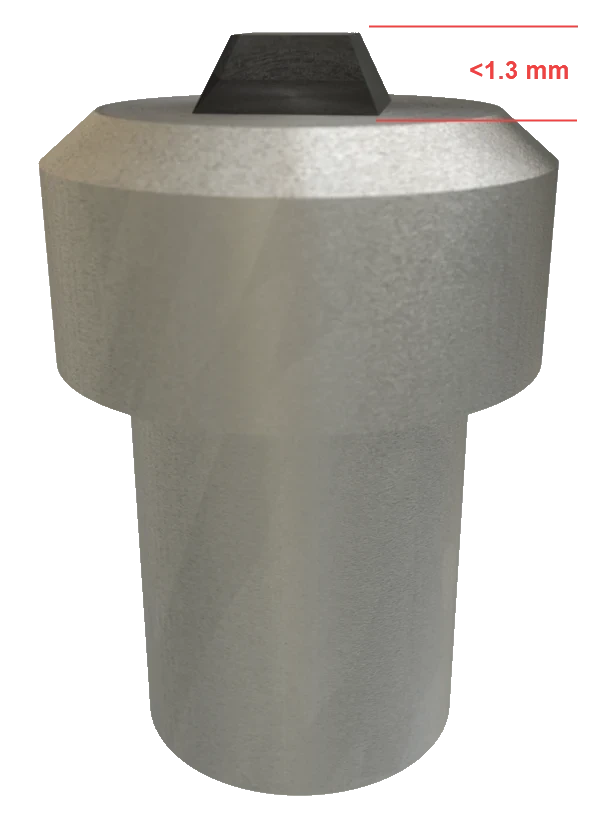
- Fix it firmly. Glue the sample to the pin with superglue or conductive epoxy, so that it cannot move during cutting.
- Give it a conductive path. Charge must be able to drain from the sample to the pin. For example, sputter-coat the sample with a conductive material.
- Keep to the height range. The top section of the pin is 2 mm high. The sample plus that top section should measure 2.1–3.3 mm. So a sample 0.1–1.2 mm high is ideal, and 1.3 mm is the maximum.
- Taller samples need a pin with a shorter top section. You can get this pin as an alternative. Taller samples are less stable and can cut less cleanly.
- Samples under 0.1 mm: if you want to cut the last 100 µm of the sample, put a thin (0.5 mm) spacer under it.
4.2 Insert, secure and remove the pin
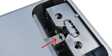 1 Insert
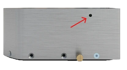 2 Secure
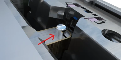 3 Remove
To insert and secure the pin:
- Remove the clear plastic knife protector, but only for as long as you need to handle the pin.
- Push the sample pin into its hole in the sample stage. Press it down firmly so that it sits fully in the hole.
- From underneath, put the supplied flat-head screwdriver into the access hole (part 9). Turn the securing screw clockwise, with your fingers only, until it is thumb-tight.
- Put the knife protector back on.
To remove the pin: turn the securing screw anticlockwise until you feel resistance. Then turn it clockwise by half a turn to release the pin. Lift the pin out.
Maintenance
5.1 Replace the knife
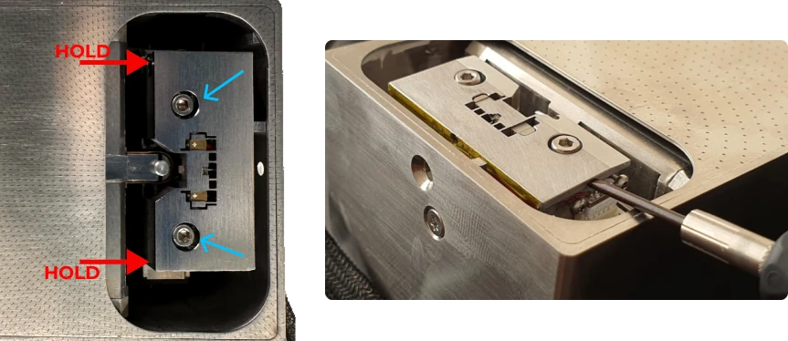
- Disconnect the microtome in Samurai, switch the controller off, and unplug the in-chamber cable from the microtome.
- Hold the knife holder firmly in the direction of the arrows while you remove its two hex screws. Holding it this way keeps any force off the cutting mechanism.
- Do not lift the holder straight up. That can damage its electrical connector. Instead, lever it gently from below with a flat-head screwdriver or a similar tool. This unplugs the connector.
- Do not touch the electrical contacts, and do not short-circuit them.
- Fit the new knife holder in the reverse order. Reconnect the cable and switch the controller on.
- Approach the sample again before you cut, because the knife has changed (Chapter 9, The approach).
5.2 Look after the diamond knife
- Keep the clear plastic protector on the knife whenever you are not cutting or handling the sample.
- Never touch the diamond edge. Keep tweezers, glue and loose debris away from it.
- After the approach and before you close the chamber, blow debris away from the block face. Use a gentle stream of dry air or nitrogen.
5.3 Keep the vacuum parts clean
Wear fresh gloves every time you handle the microtome, the in-chamber cable or the stage adapter. If they pick up contamination, wipe them with a lint-free tissue moistened with isopropanol. Let them dry completely before they go back into the chamber (Section 3.1).
5.4 Controller firmware
The microtome controller runs its own firmware, the software built into the controller. A service engineer installs updates from Settings › Microtome › Controller Firmware. You may also install one if support tells you to. Before Samurai writes anything, it checks that the firmware file really belongs to your controller (Chapter 34, Settings reference). Do not update firmware in the middle of an experiment.
Samurai at a glance
6.1 Starting Samurai
Start Samurai3 from the desktop or the Start menu. A short "Loading Samurai 3…" screen appears while the software starts its hardware service. The hardware service is the background program that controls your equipment.
What you see next depends on how Samurai was closed:
- An experiment was open last time and Settings › General › Restore Previous Experiment is on (the default): Samurai reopens that experiment. It switches to the Imaging tab and shows Restored previous experiment.
- No experiment to restore: Samurai opens on the Approach tab.
At the same time, Samurai reconnects your equipment:
- The microtome. The badge shows Connecting... while Samurai makes four attempts over about ten seconds.
- The SEM, as soon as the SEM Bridge reports that its microscope is connected.
- The PCN, but only if you switched on Auto-connect PCN.
For details of each connection, see Chapter 7, Connecting your equipment.
6.2 The window
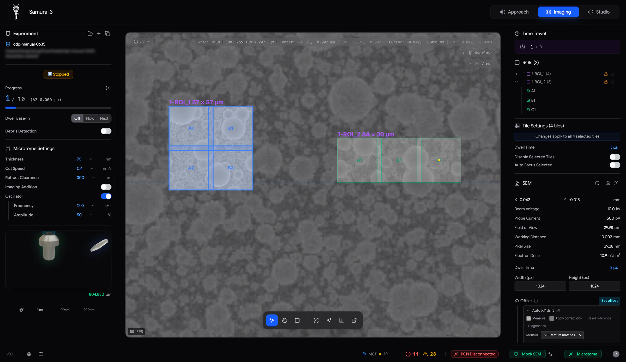 12345
12345- Workspace tabs — Approach, Imaging and, if enabled, Studio.
- Left sidebar — the experiment, run progress and microtome settings.
- Viewport — your sample, regions and images. The toolbar is at the bottom.
- Right sidebar — Time Travel, ROIs, SEM, autofocus, PCN and other panels.
- Footer — settings, manual, console and connection badges.
You use the three tabs in this order:
| Tab | Use it to | Notes |
|---|---|---|
| Approach | Bring the block face to the knife while you watch through the Digital Viewer. | Locked while Imaging Addition is active or an imaging cycle is running. |
| Imaging | Set up and run experiments. | When you enter Imaging, Samurai records the current microtome Z as the cutting plane. |
| Studio | Analyse images. | Shown only when the Studio module is enabled (Section 25.1). |
Switching tabs never stops anything. Each tab keeps its state, and a running acquisition carries on while you look at Studio. One exception: the Digital Viewer stream pauses while the Approach tab is hidden.
To expand or collapse a sidebar panel, click its title. If a control seems to be missing, scroll the sidebar. Long sidebars continue below the edge of the window.
6.3 The footer
 123456789
- Version of Samurai.
- Settings — all preferences (Chapter 34, Settings reference).
- User Manual — opens this manual in your web browser.
- AI agent chip — the MCP server, which lets outside AI agents connect to Samurai (Chapter 24, Working with AI agents).
- Console — shows the number of errors in red and warnings in yellow.
- PCN badge — shown only when the PCN module is enabled.
- SEM badge and SEM Connection Settings.
- Microtome badge.
- Cable indicator — shows whether the microtome's cable and encoder are OK. The encoder is the sensor that measures Z.
In the Studio tab, the footer also shows Search (Spotlight, Ctrl/⌘+K). While Studio is working, the footer shows a progress bar with the job name. Section 7.4 explains the badges.
6.4 The console
Click the Console button in the footer. The console opens over the right half of the window. Drag its top edge to make it taller. Click the chevron to close it.
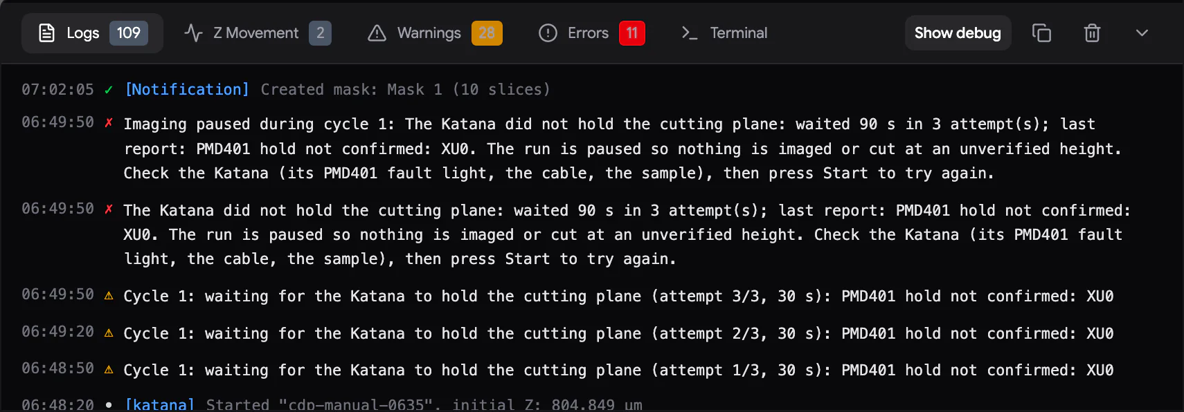
| Tab | Shows |
|---|---|
| Logs | Everything Samurai reports, newest first. Tick Show debug for extra detail. |
| Z Movement | Every microtome Z move, every Find Zero, and the position read at connection. |
| Warnings | Things that did not stop the run but deserve a look. |
| Errors | Failures that usually need you, such as lost connections, timeouts and refused actions. |
| Terminal | Raw commands to the microtome controller, for service work. |
Samurai copies every pop-up notification into the console, so you can read it again later. Warnings and errors are in plain language. The technical details go to the log file. The copy icon copies the current tab, and the bin icon clears it.
6.5 When Samurai is busy
- Busy cursor. While Samurai writes to the experiment database, the pointer shows a small spinner. Samurai holds your clicks for a moment. This is normal and usually lasts a fraction of a second.
- DB updating... If a write holds the interface for more than three seconds, a yellow label appears at the top: DB updating... (double-click to force unlock). A double-click frees the interface only. The work carries on in the background. Use it only if Samurai seems stuck.
- Long operations show a card at the top with a live progress line and a ✕ button to cancel. Syncing tile gating (writing which tiles to skip) is one example.
- Red window background. If the operating system reports that the window stopped responding, the background turns dark red until the window recovers. The console notes how long it was frozen.
6.6 Notifications
Notifications appear at the bottom right. Most disappear by themselves. Important ones stay until you close them. Some carry an action, such as Reconnect, Clear PCN fault or Clear cut record. The console also keeps every notification.
6.7 Closing Samurai
Close the window as usual. Samurai asks Close Samurai? Click Close to confirm. If Studio has unsaved changes, Samurai saves them first and shows "Saving Studio changes before closing…". If that save fails, Samurai stays open, so nothing is lost.
6.8 Log files
Samurai writes one log file each time it starts. The log uses local time. Support will usually ask for this file.
| System | Folder |
|---|---|
| Windows | %LOCALAPPDATA%\Samurai3\logs |
| macOS | ~/Library/Application Support/Samurai3/logs |
The file is named app-<date>T<time>.log. When Samurai starts, the previous logs move into the old subfolder.
6.9 System requirements
| Item | Recommendation |
|---|---|
| Operating system | Windows 10 or 11, 64-bit |
| Memory | 16 GB or more (8 GB minimum). Large Studio datasets work better with 32 GB or more. |
| Storage | A fast SSD with room for your image data. An acquisition can reach hundreds of gigabytes. |
| Display | 1920 × 1080 or larger |
Connecting your equipment
Samurai talks to three kinds of equipment, each in its own way:
- the microscope, through the Universal SEM Bridge
- the microtome controller, over USB, or over the network (TCP) for a simulator
- optional accessories through their own panels: the PCN needle, the Kensho detector and EDS
7.1 The Universal SEM Bridge
The SEM Bridge is a small companion program. It runs on the microscope PC, or on a support PC that can reach the microscope. It speaks the microscope maker's own interface. It gives Samurai one connection that works the same way for every brand. You choose the microscope in the bridge, not in Samurai.
Microscopes the bridge supports
| Maker | Choices in the bridge's SEM list | Notes |
|---|---|---|
| TESCAN | TESCAN | Full integration through SharkSEM. |
| Thermo Fisher | Quanta, Nova, Apreo, Scios | Enter the microscope PC's address. The bridge PC needs the xT client components. |
| Zeiss | Zeiss SmartSEM | The bridge runs on the SmartSEM PC. |
| Hitachi | SU3839 (SU3800/SU3900 family), SU5000, SU7000 | |
| CIQTEK | SEM2000, SEM3100/3200, SEM3300, SEM4000/5000, SEM6000 | |
| JEOL | EXCS, MEC, EIK | |
| Phenom | Pharos | Needs the instrument ID or IP address, and the login details. |
| Any other SEM | Generic SEM | Starts each image with a recorded click in the microscope's own software. Then passes the new image to Samurai (Section 7.6). |
| — | Mock SEM | A simulated microscope for training and testing. |
To connect the bridge to the microscope:
- Start the microscope's own software first, for example TESCAN Essence, Zeiss SmartSEM or the Thermo Fisher xT UI.
- Start the Universal SEM Bridge.
- Choose your microscope in the SEM dropdown. Enter its address, and its port if asked.
- Click Connect. When the button turns green and reads Connected, the bridge is ready.
- Leave the bridge running while you use Samurai.
The bridge's status strip has a line Samurai3 connect to: … with the address and port to type into Samurai. Once Samurai has attached, the strip shows Samurai3: Connected.
7.2 Connect Samurai to the bridge
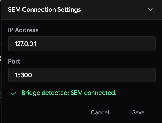
- In Samurai's footer, click the gear next to the SEM badge. SEM Connection Settings opens.
- Enter the bridge's IP Address and Port. If the bridge runs on the same PC, use
127.0.0.1. If not, use the address shown on the bridge's Samurai3 connect to line. The default port is15300. - Watch the line under the fields. A green ✓ with Bridge detected; SEM connected. means everything is ready.
- Click Save.
Within a second, Samurai attaches by itself. The SEM badge turns green and shows the microscope's name. There is no Connect button for the SEM in Samurai. Samurai attaches whenever the bridge reports that its microscope is connected. To disconnect the microscope, disconnect it in the bridge.
If the line under the fields shows a red ✗, read its message:
| Message | What to do |
|---|---|
| Bridge detected; SEM not connected. | Click Connect in the bridge. |
| Bridge not detected at … | Start the bridge, or check the address and port. |
| TCP endpoint answered, but it is not the Universal SEM Bridge … | Another program is using that port. Check the port shown in the bridge. |
| Port must be between 1 and 65535. | Correct the port number. |
7.3 Connect the microtome
If Auto-connect Microtome is on (the default), Samurai connects to the controller when it starts. To connect by hand, click the red Disconnected badge in the footer.
Settings › Microtome › Connection sets how Samurai reaches the controller:
- USB (normal): Samurai scans the serial ports and finds the controller by itself.
- TCP: Samurai connects to a network address. Use this for the microtome simulator, and enter its IP Address and Port.
The change takes effect at the next connection.
To disconnect, click the green Microtome badge. It turns orange and asks Disconnect? Click ✓ to confirm. To cancel, click ✗ or press Esc.
If the USB connection drops unexpectedly, a USB Disconnected notification stays on screen with a Reconnect button. Samurai never reconnects a USB microtome by itself. Check the cable, then click Reconnect or the badge.
7.4 Reading the badges
| Badge | Colour | Meaning | Click it to |
|---|---|---|---|
| SEM | Green, with the microscope name | Attached through the bridge. Hover over it to see the address. | — |
| Red, SEM Disconnected | No bridge, or the bridge's microscope is not connected. | — (use the gear) | |
| Microtome | Green | Connected. | Disconnect (confirm with ✓). |
| Yellow, Connecting... | Samurai is scanning the ports. | — | |
| Red, Disconnected | Not connected. | Connect. | |
| PCN | Green / red, PCN Disconnected | Green: the PCN controller answers. Red: it does not answer. | Green: disconnect. Red: connect. |
| Cable ✓ × ? | Green ✓ | The controller reports that the microtome cable and the encoder signal are OK. The encoder is the sensor that measures Z. | — |
| Red × | The controller lost the microtome cable or encoder signal. It retracts the knife and stops the motor. | — | |
| Grey ? | No status from the controller yet, because it is not connected. | — |
A green badge proves only that Samurai is talking to the equipment. It does not prove that the beam is on, the detector is ready, the focus is right or the chamber is clear. Check those on the microscope.
7.5 Optional equipment
A service engineer switches on optional modules in Settings › Service › Enabled Modules. The modules are Studio, PCN, Kensho BSED and EDS (Oxford AZtec). Once a module is enabled:
- The PCN connects from its footer badge. Its connection settings are in Settings › PCN (Chapter 20, The PCN needle).
- Kensho and EDS connect from their own panels in the Imaging tab (Section 19.3, Chapter 22, EDS maps with Oxford AZtec).
7.6 Generic SEM: microscopes without an interface
If your microscope has no supported control interface, choose Generic SEM in the bridge. The bridge then works like a patient assistant sitting at the microscope PC:
- In the bridge's AutoClicker card, record the point on the screen where the microscope software's acquire button is. Then choose how the bridge knows that the image is finished:
- a new file appears in the image folder
- a fixed delay after click has passed
- a screen box settles (a chosen box on the screen stops changing)
- Set the bridge's Image folder to the folder where the microscope software saves its images. Use Test Capture to check it.
- In Samurai, the SEM badge turns green, as for any microscope.
For each cycle, the bridge clicks, waits, and sends Samurai the new image. Samurai still has full control of the microtome and the cutting. But it cannot move the SEM stage, set the beam or choose the field of view. In this mode:
- Samurai takes one image per cycle.
- You do not draw ROIs.
- Samurai creates the cycles when you press Start.
- The SEM and Autofocus panels are hidden.
The Scripting panel is still available for any extra steps (Chapter 23, Scripting).
Working in the viewport
The viewport in the middle of the Imaging tab is a map of the microscope stage. Everything in it is drawn at its real stage position. This includes the SEM crosshair, your regions of interest (ROIs) and their tiles, preview images, acquired images and masks. Each tile is one image position in an ROI. Studio's viewport works the same way, so what you learn here applies there too.
8.1 The toolbar
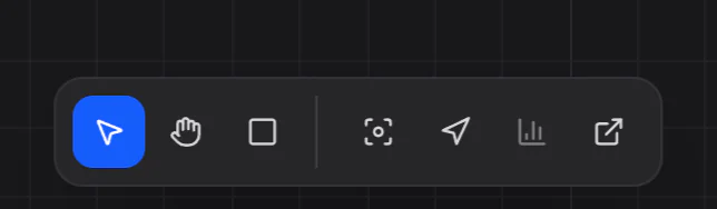 1234567
- Select (V) — pick and move things.
- Hand (H) — pan the view. It never selects or moves anything.
- Draw ROI (D) — drag a rectangle to create a region of interest.
- Cycle through views (0) — show each ROI in turn, then all ROIs, then the SEM position.
- Follow stage — keep the SEM stage position in the centre.
- Histogram — show or hide the display levels (Section 16.1).
- Open a read-only viewport window — a second view for another monitor.
Two more buttons appear only when they apply. Draw mask shape appears while a drawn mask is selected (Section 21.3). A follow target switch appears while Follow stage is on.
You can use Draw ROI only when an experiment is open and its microscope is connected. If a button is greyed out, hover over it to see why. You may see Connect SEM first, Create an experiment first or Connected SEM does not match experiment.
8.2 Pan and zoom
Samurai works like Figma and other design tools: scrolling moves the view, and zooming needs a pinch or a modifier key.
| To | Do this |
|---|---|
| Pan | Scroll with the mouse wheel or a two-finger swipe. You can also drag with the Hand tool, hold Space and drag, or drag with the middle mouse button. |
| Pan sideways with a mouse | Shift + scroll. |
| Zoom smoothly | Pinch on the trackpad. |
| Zoom in steps | Ctrl/⌘ + scroll. Each notch zooms by 15 %. Add Shift for fine 3 % steps. |
| Show image pixels 1:1 | Point at the viewport and press 1. Press 2, 3 or 4 for 2:1, 3:1 or 4:1. The zoom is based on the selected tile or ROI. If nothing is selected, it is based on the image in the middle of the view. |
| Show your ROIs | Press 0 again and again. The view shows each ROI in turn and selects it. Then it shows all ROIs, then the SEM stage position. |
| Go to the SEM stage | Press the . key on the numeric keypad. |
The view stops as soon as your fingers stop. It does not glide on. Zoom stays centred on the pointer. While Follow stage is on, it zooms around the centre instead.
The information bar
The line at the top right describes what you are looking at:
Grid: 10μm │ FOV: 132.3μm × 114.7μm │ Center: 1.839, 0.209 mm │ Cursor: …
- Grid — the spacing of the most visible grid lines.
- FOV — the width and height of the visible area.
- Center — the stage position at the middle of the viewport.
- Cursor — the stage position under the pointer, when the pointer is inside the stage limits.
If the experiment has an XY correction (Section 19.1), a dimmer (SEM: …) value follows. It is the corrected position that the microscope stage really drives to.
Following the stage
Click Follow stage to keep the SEM stage position in the centre of the viewport while the microscope moves. Your zoom stays the same. While it is on, a second button chooses what to follow:
- the stage crosshair (the default), or
- the last acquired image. This shows you where each image really landed.
Following switches off when you pan by hand, press 0 or jump to a saved view. To make the view glide instead of jump, turn on Settings › Advanced › Viewport Tracking Smoothing.
Samurai remembers the view of each experiment. It restores the view when you reopen that experiment.
8.3 Select things
With the Select tool:
| Gesture | Result |
|---|---|
| Click a tile | Selects that tile. |
| Ctrl/⌘ + click | Adds the tile to the selection. If it was already selected, removes it. On macOS use ⌘, because Control-click opens the right-click menu. |
| Alt + click | Removes the tile from the selection. |
| Double-click a tile | Selects its ROI. |
| Click inside an ROI, not on a tile | Selects the ROI. |
| Click empty space | Clears the selection. |
| Drag across tiles | Box selection (see below). |
| Shift + drag | Draws a freehand lasso. It selects the tiles it touches. |
| Shift + click, click, click… | Draws a polygon that selects the tiles it touches. To close it, click the first point (it turns green and says Click to close) or press Enter. Esc or any normal click discards the polygon. |
| I | Inverts the tile selection inside its ROI. |
The direction of a box drag matters:
A box, lasso or polygon selects tiles from one ROI only. If a box covers almost all of an ROI, Samurai selects the ROI itself. To add to the selection, hold Ctrl/⌘ as you release. To remove from it, hold Alt.
The ROI panel shows the same selection. When you are not typing in a text field, the arrow keys move through the ROI list:
- ↑ ↓ move up and down the list.
- → expands an ROI to show its tiles.
- ← collapses it.
8.4 Move and resize
To move something, select first, then drag. The click that selects an object never moves it.
- Click the ROI, or double-click one of its tiles, to select the ROI. Its outline turns blue.
- Press on the selected ROI and drag. The move starts only after the pointer has moved a few pixels. So a plain click still selects a tile.
- While you drag, you can hold:
- Shift to move only along X or only along Y. A ↔ or ↕ badge appears next to the pointer.
- T to snap the move to whole tile steps.
- G to snap the corner to the grid lines you can see. A hint above the toolbar reminds you of these keys.
- Release to finish, or press Esc to cancel.
Samurai records each move in the undo history, so you can undo it with Ctrl/⌘+Z. Once cycles exist, a move applies from the live cycle onwards. The live cycle is the cycle the run is on, or will start with. This happens whichever cycle you are viewing, because an ROI's position is physical (Section 14.3). You cannot move a locked ROI (Section 13.1).
Resizing. A selected ROI has a blue handle at its bottom-right corner. Once cycles exist, it also has a violet handle at the top-left. Drag a handle to add or remove whole rows and columns of tiles. The tiles you already have keep their names and positions. Section 13.5 explains why.
Masks and references move the same way: select, then drag. Their drag starts at once, with no snapping. You can select a locked mask or reference, but you cannot drag it (Chapter 21, Masks and tile gating).
8.5 Selection Scope for overlapping objects
When ROIs, masks and references overlap, it can be hard to click the one you want. Selection Scope limits the viewport to one object for a while.
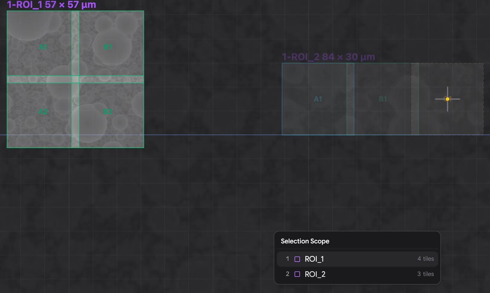
- With the Select or Hand tool, point at the viewport and press ' (apostrophe). Or right-click and choose Selection Scope.
- Choose an ROI, a drawn mask, a 2D reference or a 3D reference. Click it, press its number 1–9, or use the arrow keys and Enter.
- A small Scope: label appears at the top of the viewport. Everything else is dimmed, and you cannot click it.
- To clear the scope, press ' again, press Esc, or click the × on the label.
A scope is temporary. It clears itself if you switch to Draw ROI, hide the object or open another experiment. It has nothing to do with a mask's saved Gating ROIs.
8.6 Right-click menus
Right-click in the viewport to open a menu. Its items depend on what is under the pointer.
| Right-click on | Menu items |
|---|---|
| A tile | Highlight in Outliner · Reveal in Explorer · Re-acquire in This Cycle · Drive SEM Stage Here · Drive PCN here · Zoom 1:1 · Selection Scope |
| A mask or reference | Highlight in Outliner · Drive SEM Stage Here · Drive PCN here · Zoom 1:1 · Selection Scope |
| An SEM preview | Reveal in Explorer · Drive SEM Stage Here · Drive PCN here · Zoom 1:1 · Selection Scope |
| Empty space | Drive SEM Stage Here · Drive PCN here · Selection Scope |
- Drive SEM Stage Here moves the microscope stage to the tile's centre, or to the exact point you clicked. The first time a move is longer than 1 mm, a Large Movement Warning appears. It shows where the stage will go and asks you to click Continue.
- Reveal in Explorer opens the folder that holds the tile's files.
- Re-acquire in This Cycle puts the tile back in the queue of the cycle that is being acquired (Section 15.9).
- Drive PCN here appears when the PCN gas needle is shown (Section 20.5).
8.7 What the colours mean
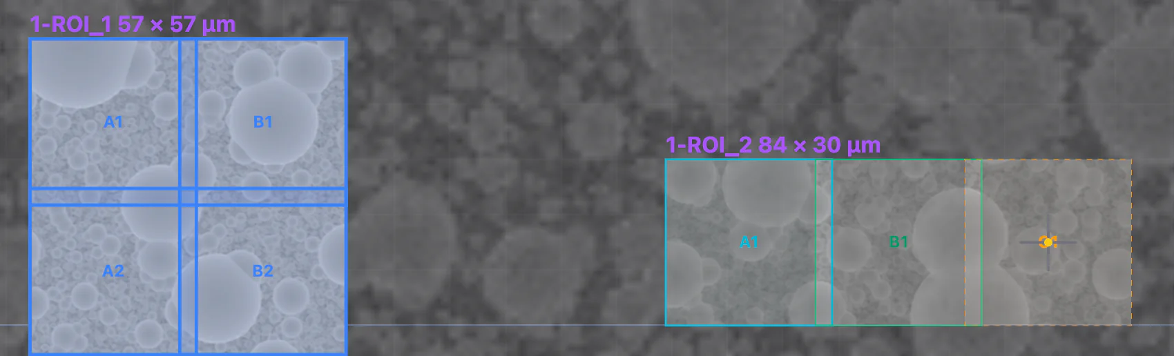
| Tile appearance | Meaning |
|---|---|
| Green outline, green name | A normal tile. |
| Blue outline and tint | Selected. |
| Orange dashed outline | Disabled. Samurai will skip it (Section 12.5). |
| Cyan outline | An autofocus tile. It pulses cyan while Samurai focuses on it. |
| Pulsing green | Samurai is imaging this tile now. A green line along its bottom edge grows during the exposure. |
| Blue line along the bottom | Samurai is still writing the image to the image store on disk. |
| Pulsing blue | Samurai is collecting an EDS map at this tile. |
| Red | The capture failed. |
| Red dashed outline | A mask would gate (skip) this tile. You see this while Tile Gating is ticked in Overlays (Section 21.7). |
Other things you may see:
- ROI names in purple above each ROI. The name includes the size of the ROI's tile grid, for example
ROI_1 57 × 30 μm. The selected ROI's name turns blue. - The SEM crosshair marks the stage position. It pulses when you centre the view on it. Its dot turns orange while the stage is moving.
- SEM LIVE SCAN — a pale blue frame with a moving band. It shows where the microscope is scanning live. This is a scan started from the microscope software, not from Samurai.
- Stage Limits — a red dashed rectangle at the edge of the stage's travel.
- Previews at half strength. SEM previews and manual tile captures are drawn at 50 % opacity until you select them. This way they never hide the acquired data (Section 11.2).
- A sepia frame around the whole viewport when you look at a past cycle. A purple frame when you look at a future cycle (Section 14.2).
- Loading imagery… with a hatched pattern while Samurai reads images from disk. Tiles that were never acquired stay empty.
8.8 Overlays and saved views
The Overlays list at the top right sets what the viewport shows. Samurai saves your choices with the experiment.
| Overlay | Default | Shows |
|---|---|---|
| Grid | on | The coordinate grid. Each click on the swatch beside it changes the grid's strength and colour. |
| ROIs | on | ROI names and outlines. The arrow beside it reverses which ROI is on top, both on screen and for clicks. |
| ↳ Tiles / Tile Names | on | Tile outlines and their names. |
| Overviews | on | Numbered SEM previews. |
| Acquired Images | on | Images from the runs. new↑ / new↓ chooses whether newer tiles are drawn over older ones. blend fades neighbouring tiles into each other where they overlap. This changes only the display. |
| Original / Flatfield | Original | Show images with or without flat-field correction (Section 16.2). It evens out brightness and contrast across each tile. |
| Tile Gating | on | The live gating decision of your masks: which tiles they would skip (Section 21.7). |
| Dwell Time | off | Each tile's dwell time, as bars or a heatmap. Only on microscopes that use dwell time. |
| Diff | on | Difference images and badges from debris detection (Chapter 18, Debris detection). |
Views, below Overlays, saves the current pan and zoom as a bookmark. Type a name and click Save. Saving with the same name overwrites the old view. Click a saved name to go back to that view. Click ✕ to delete it. Views are stored with the experiment.
8.9 A second window
Click Open a read-only viewport window to show the acquisition in a separate window. This is useful on a second monitor or a wall screen.
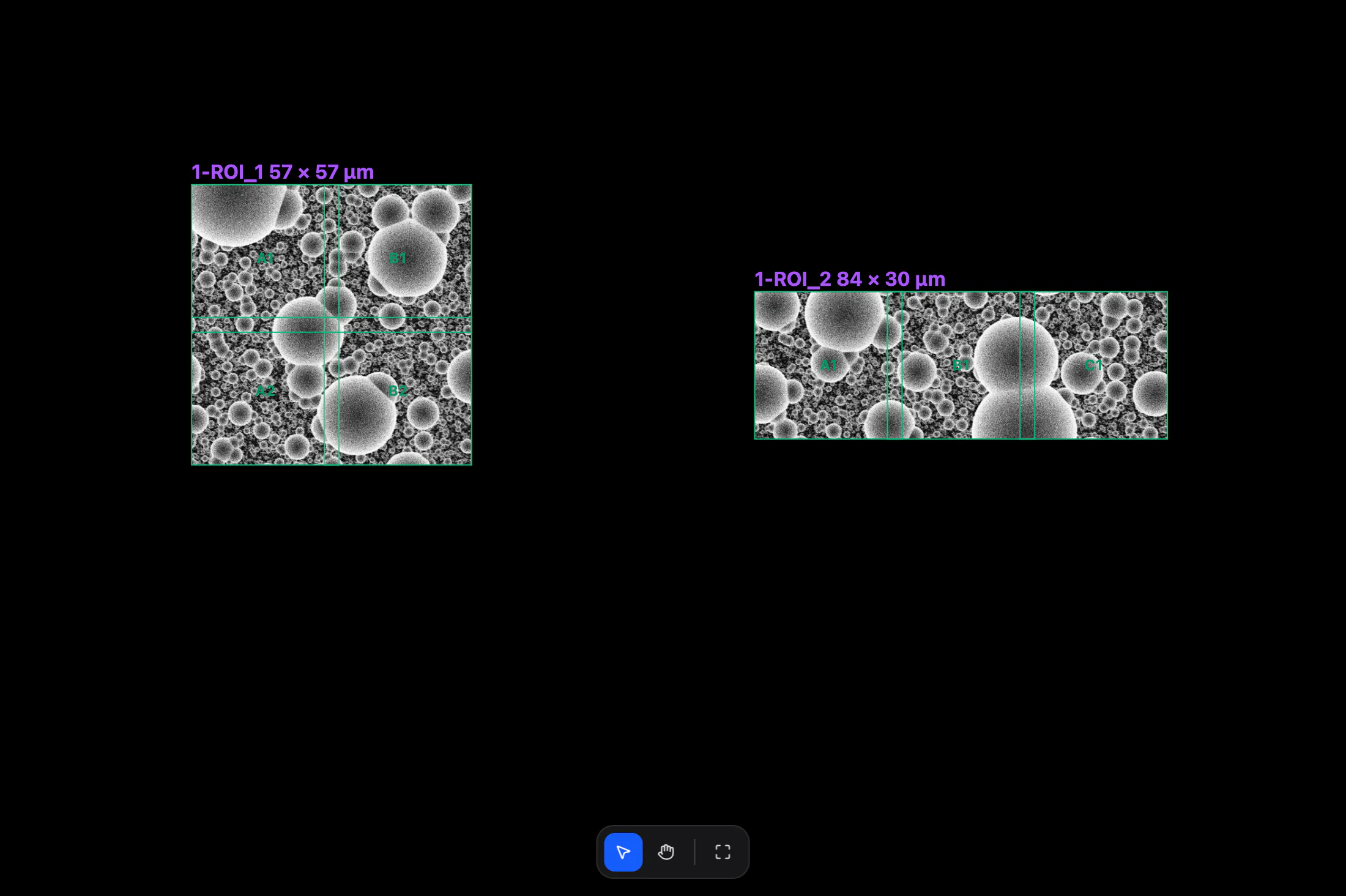
The window shows the same images as the main window, with the same display levels. It also shows the same cycle, including during Time Travel. It starts at the main window's view. After that, it has its own view. Pan and zoom it as you like with its own Select tile, Pan and Fit all tiles buttons. You cannot edit anything from it. It closes when Samurai closes.
The approach
Before you can image a new sample, you must bring its block face exactly to the knife. This height is the cutting plane. There, the knife shaves a thin, even section from the whole surface. Bringing the block there is the approach. You do it in the Approach tab, with the chamber open and the Digital Viewer camera on the microtome. You watch the knife and the block through the camera.
9.1 The Approach tab
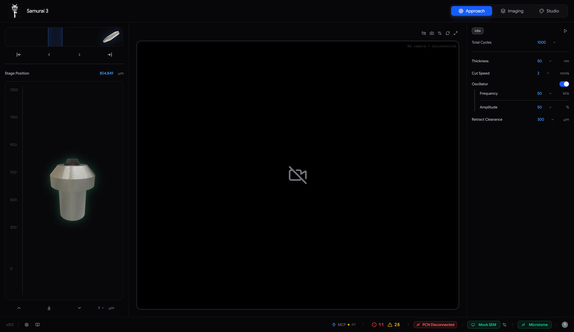 1234567
- Knife track — the position of the diamond knife, and the blue cutting window.
- Knife buttons — Cut, jog left, jog right and Retract. Hold a jog button to move the knife.
- Stage Position — the sample height in µm. Click the number to type a new height.
- Stage scale — the sample pin moves up and down with Z.
- Stage buttons — up, Zero (Find Zero), down, and the step size.
- Camera — the Digital Viewer's picture, with its buttons at the top right.
- Approach panel — status, Start/Stop, cycles and cutting parameters.
The knife and stage controls are greyed out while the microtome is disconnected. The same happens while the stage is raised for imaging (Imaging Addition, Section 15.2). The controls also lock while the microtome is busy with an approach, a cut, a Find Zero or an imaging run. Hover over the sidebar to see why.
9.2 Z and Find Zero
The stage height, Z, is shown in micrometres under Stage Position. A higher value means the sample is higher, so it is closer to the knife. The stage travels from 0 to 1300 µm.
Z comes from a relative encoder. The controller knows how far the stage has moved since it last found its reference. It does not know where the stage is in absolute terms. Find Zero gives it that reference.
To find zero: make sure nothing is in the stage's path. Then click the Zero button between the up and down arrows. The stage drives down until it reaches its lower stop and cannot go further. It then moves back up by about 5 µm and calls that point 0.000. This can take up to a minute, and you cannot interrupt it. The console then reports Stage zero found.
Run Find Zero in these cases:
- The controller was switched off or lost power. Z then reads 0, wherever the stage really is.
- Samurai reports that the motor driver reset and needs re-homing. Samurai refuses to cut until you run Find Zero.
- You are not sure where the stage is.
9.3 Move the stage
- Click or to move the stage up or down by one step. Choose the step in the drop-down beside them: 0.5, 1, 10 or 100 µm.
- Or click the blue Stage Position number, type a height and press Enter. The stage moves to that height. Esc cancels.
Use large steps only when the sample is far from the knife. As you get close, change to steps of 1 µm or 0.5 µm. The Z Movement tab of the console lists every move.
9.4 Move the knife
The track at the top of the left sidebar shows the diamond knife. The knife cuts from right to left. The right end of the track is fully retracted (clear of the sample). The left end is fully forward.
| Control | What it does |
|---|---|
| Cut | Makes one stroke. The knife moves fast to the window start, through the window at the cut speed, then on to the fully forward position. The knife does not oscillate (vibrate), and the stage does not rise. The knife stays forward, so press Retract afterwards. |
| / | Hold to jog the knife left or right. |
| Retract | Moves the knife back to the fully retracted position. This is always allowed, because it moves away from the sample. |
| Drag the diamond | The knife follows the pointer. For precise moves, hold Shift. The pointer hides and the knife moves in much finer steps. |
| A / D (hold) | If Settings › Microtome › Knife Jog Keyboard Shortcuts (A/D) is on, these keys jog the knife left or right. |
Set the cutting window
The cutting window is the see-through blue band on the knife track. It is where the knife cuts. Every cut moves through the window at the cutting speed and moves fast outside it. This includes cuts during the approach, manual cuts and the cut in every imaging cycle. The window must cover the whole block face.
- Double-click the left or right edge of the blue band. The edge turns bright blue and the pointer becomes ↔.
- Drag the edge to where you want it.
- Release. The edges can no longer be dragged. To adjust once more, double-click again.
Samurai saves the window automatically. The Approach and Imaging tabs share the same window. You cannot change it while an approach is running.
9.5 The camera
The centre of the tab shows the Digital Viewer's picture. The camera is off when Samurai starts. It also stops whenever you leave the Approach tab. To see the picture, click Start camera.
| Button | Use |
|---|---|
| Start / Stop camera | Connects the camera and shows its picture, or stops it. |
| Switch camera | Moves to the next supported camera, if more than one is connected. |
| Settings | Zoom, Gamma, Gain, Auto White Balance and Flip Vertical. Double-click the Gamma or Gain label to reset it. |
| Reset view | Zooms back to 1×. |
| Fullscreen | Hides the right sidebar to make the picture bigger. |
Scroll over the picture to zoom it (1× to 5×). Drag to pan. Exposure and frame rate are in a separate Viewer Settings window. A service engineer can open it from Settings › Service.
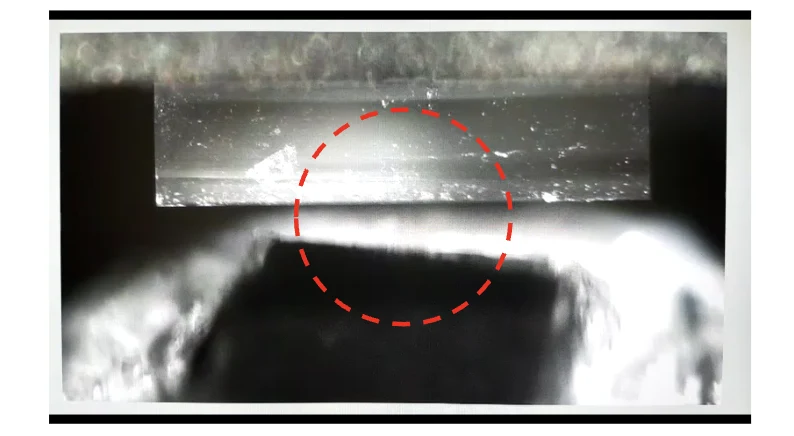 Before contact
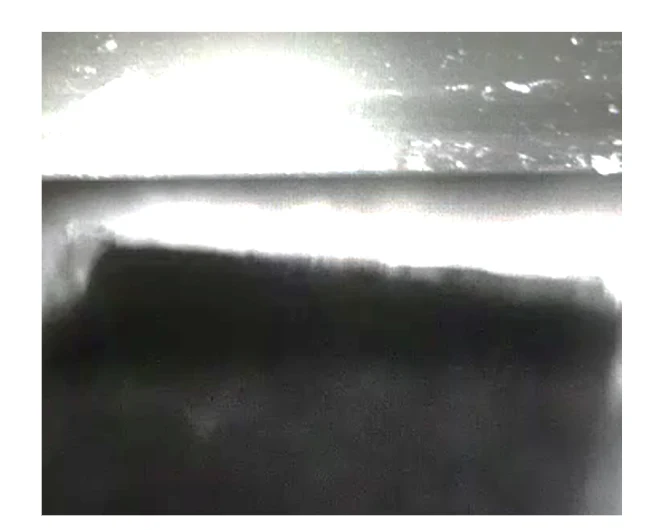 At the cutting plane
9.6 Approach parameters
The right-hand panel runs the automatic approach.
| Setting | Default | Range | What it does |
|---|---|---|---|
| Total Cycles | 1000 | — | How many cuts to make. Goes back to 1000 each time Samurai starts. |
| Thickness | 50 nm | 1–200 nm | How far the stage rises before each cut. |
| Cut Speed | 0.2 mm/s | 0.01–10 mm/s | Knife speed inside the cutting window. |
| Oscillator | on | on / off | Vibrates the knife while cutting. |
| ↳ Frequency | 50 kHz | 0–100 kHz | Presets: 5, 12 and 37 kHz. |
| ↳ Amplitude | 50 % | 0–100 % | How strongly the knife vibrates. |
| Retract Clearance | 300 µm | 1–9999 µm | How far the stage drops after each cut, before the knife returns. Max drops it to Z = 0. |
Click a blue value to type a new one, or click its chevron to choose a preset. Samurai saves the values automatically. You can change them during a run. Each change applies from the next cycle.
9.7 What one approach cycle does
- The knife moves quickly to the start of the cutting window.
- The stage rises by Thickness.
- The oscillator starts and the knife cuts through the window at Cut Speed.
- The oscillator stops.
- The stage drops by Retract Clearance.
- The knife returns quickly to the window start. On the last cycle, it goes all the way back to the retracted position.
- The stage rises back to the cutting height.
Click Start to begin. Samurai does not ask you to confirm. The status reads Running, and Progress counts the cycles.
Click Stop to finish. The status shows Stopping... while the current cycle completes: the cut, the clearance drop and a full knife retract. Then the run ends, and the status shows Idle. Stop never interrupts a cut in the middle of a stroke. Each Start counts from cycle 1 again.
If Start is greyed out, the microtome is disconnected, the stage is raised for imaging, or the microtome is busy. If an approach starts and then goes back to Idle at once, read the Errors tab of the console. The line begins Approach failed:.
9.8 Step by step: approaching a new block
Coarse approach with the chamber open
- Check the footer. Microtome should be green, and the cable indicator should show ✓.
- Put the Digital Viewer on the microtome and click Start camera. Adjust gamma and gain until you can see the knife edge and the block face.
- Click Retract so the knife is fully back.
- If the stage has no reference yet, click Zero to find zero (Section 9.2).
- Set the cutting window so the blue band covers the whole block face (Set the cutting window).
- Move the diamond over the sample. Drag it, or hold the jog buttons.
- Raise the stage in steps while you move the knife back and forth over the block. Watch for the blade's shadow or reflection on the block face.
- Make the step smaller as you get closer: 100, then 10, then 1 µm. Continue until the reflection is about to meet the blade. Never let the knife take a large slice.
Fine approach with automatic cycles
- In the approach panel, set Thickness, a fast Cut Speed and Total Cycles. For example, use a thickness of 200 nm for a fast first approach, and a cut speed of 5 mm/s.
- Click Start and watch the knife and the block through the camera.
- The knife usually cuts one corner first. Wait until it cuts the entire block face, then click Stop.
After pump-down
- Click Stop camera, then remove the Digital Viewer.
- Blow debris off the block face with a gentle stream of dry air or nitrogen.
- Close the chamber and pump down.
- Lower the stage by 2 µm, because the sample can change slightly in the vacuum. Click twice at a 1 µm step, or type the new height.
- When the vacuum is ready, run approach cycles until you have cut at least 2 µm. This makes sure the knife meets the surface again. (Material removed = cycles × thickness.)
- Finish with a few slow cuts, for example at 0.1 mm/s. This leaves a smooth surface for imaging.
- Switch to the Imaging tab. Samurai records the current Z as the cutting plane.
9.9 If something goes wrong
| What you see | What it means and what to do |
|---|---|
| Red ⚠ next to Stage Position | The last Find Zero failed. Hover over the ⚠ to see why. Check that nothing blocks the stage, then try again. |
| Console: Stage move rejected — no recent position data from the microtome | Samurai no longer receives position data from the controller. Check the USB cable and the footer badge. |
| Console: Stage motor overheated … retrying | The motor driver got hot. Samurai waits and tries again at a lower speed. If this keeps happening, reduce the load. Check the sample and the cutting speed. |
| Cable indicator turns red | The controller lost contact with the microtome cable or the encoder. Before cutting, lower the stage by more than 2 µm and approach again. |
| Cut blocked while the PCN is disconnected | When the PCN module is on, a cut needs the PCN to confirm that its gas needle is safe. Reconnect the PCN (Chapter 20, The PCN needle). |
| Approach returns to Idle straight away | Read the Errors tab of the console. Look for the line Approach failed: … |
Experiments
An experiment holds everything about one run on one sample. This includes its regions of interest and tiles, its cycles and their settings, every image, and the progress so far. You create and open experiments in the Experiment panel, at the top of the left sidebar in the Imaging tab.
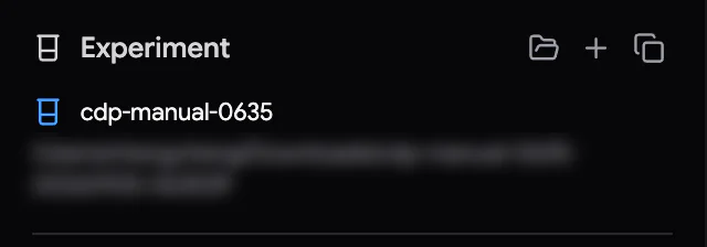
The panel has three buttons: Load experiment from file, New experiment and Save as copy. You cannot use them while imaging is running.
10.1 Create an experiment
First, the microscope must be connected. An experiment remembers which microscope it belongs to.
- Click New experiment. A form opens in the panel.
- Type a name in Experiment Name.
- Click the folder button (Select save folder) and choose where the images should go. Save to: shows the folder you chose. Samurai remembers your last choice.
- If another experiment is open, you can tick Copy ROIs from ‹its name›. The new experiment then starts with that experiment's regions of interest (Starting from another experiment's ROIs).
- Click ✓ Create experiment, or press Enter.
Samurai creates a new folder inside the one you chose. The folder name is the experiment name plus the date and time, for example mouse-cortex-20260925-101500. Samurai then opens the new experiment at once. If Samurai cannot write to the folder, it tells you before it creates anything.
- Same name again? If an experiment with the same name already exists, Samurai asks before it creates a second one (Create Anyway). Samurai keeps both as separate experiments, but the matching names may confuse you later.
- Network drives. Some microscopes write their images directly to a shared folder. For these, Samurai reminds you that the save location must be a network drive that the microscope PC can reach.
Starting from another experiment's ROIs
Copy ROIs from … copies the regions of interest and their tiles. This includes their positions, sizes, overlap, dwell, autofocus marks and disabled tiles. It does not copy their images or history. The copied ROIs start unlocked, and every tile starts fresh. Before you use them, check the positions against the new sample.
10.2 Open an experiment
Click Load experiment from file. The dialog opens in Samurai's experiments folder. You can choose:
- the experiment's database file (
.db), or - the
.samurai3-dbfile inside the experiment's data folder. This small file points to the database. Choosing it is often easier, because you know where the data folder is.
Before loading, Samurai checks the microscope. If the experiment was created on a different microscope from the one connected, Samurai does not load it. It shows SEM does not match experiment. Connect the right microscope and try again.
If Samurai was closed or crashed during a run, the run opens as Stopped. A note in the console names the last tile that finished. Press Start to continue from there (Section 15.10).
10.3 Save a copy
Click Save as copy to make a copy of the open experiment. For example, do this before you try risky changes, or to give a dataset to someone else.
- Type a name for the copy and choose a folder. Samurai suggests ‹name›_copy.
- To copy the image data too, tick Include images (if any exist). Leave it off to copy only the settings, ROIs and cycles.
- Click ✓ Save copy. The original stays open. To switch to the copy, click Open copy in the green box.
The copy is a completely separate experiment with its own identity.
10.4 What is saved, and when
Everything saves automatically. There is no Save button. Samurai writes each change to the experiment's database straight away, then reads it back. So what you see is what is stored. While Samurai writes, the pointer briefly shows a small spinner (Section 6.5).
Saved with the experiment:
- ROIs, tiles and all their settings, for every cycle;
- cycles, their microtome settings and progress;
- masks and references, and their gating (which tiles they skip);
- the viewport's position, overlays and saved views, and the histogram levels.
Some things are saved once for the whole installation instead, in Samurai's settings. These are the Approach tab's values, the cutting window, the Settings dialog and your connection settings.
10.5 Where the files are
An experiment has two parts on disk:
- The database (
.db) is kept on the Samurai PC's local disk, in Samurai's experiments folder. On Windows, this is%LOCALAPPDATA%\Samurai3\experiments. Keeping it local protects it if a network drive disconnects. - The data folder is the one you chose. It holds the images and everything else made during the run. The acquired images are in
acquisition.zarr. There is one image store per ROI, which holds all of that ROI's images (Chapter 33, Data and files).
10.6 Changing experiments
When you open or create another experiment, Samurai does three things:
- It clears the undo history, because the history belongs to the experiment you left.
- It turns the PCN Off and leaves the gas needle where it is (Section 20.3).
- It switches off every enabled scripting sequence. This way, automation set up for one experiment does not run in the next. The sequences themselves are kept. If the experiment you open carries its own sequences, it brings them back instead.
You cannot open or create an experiment while imaging is running.
Imaging parameters and previews
Good serial block-face data needs a balance between three things that pull against each other:
- how thin you cut
- how much signal each image gets
- how much beam damage the block can take
This chapter shows where each setting is and how to take preview images. It also helps you choose good starting values.
11.1 Who controls what
Samurai and the microscope share the work:
| Set it on the microscope | Set it in Samurai |
|---|---|
| Beam voltage (kV), probe current, detector, focus and stigmation. During a run, Samurai's autofocus can correct focus and stigmation (Chapter 17, Autofocus and autostigmation). | Where to image: the ROIs (regions of interest) and their tiles. See Chapter 12, Regions of interest and tiles. |
| The live view you use to find your sample | How each tile is imaged: pixel size, image size, dwell time or scan mode, and overlap (Section 12.3) |
| When things happen: cycles, cutting, autofocus, checks and scripts |
The SEM panel is in the right sidebar of the Imaging tab. It shows what the microscope reports. You also use it to take preview images.
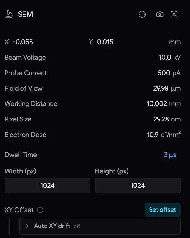 12345
12345- Center viewport to stage position.
- Grab Image takes an image at the current field of view. Grab Image at 100x takes a zoomed-out overview.
- Readouts from the microscope: stage X and Y, beam voltage, probe current, field of view, working distance, pixel size and electron dose. You cannot change them here.
- Preview settings: the dwell time (or frame time or scan mode) and the image size. They apply only to the Grab Image button.
- XY Offset — corrects a shift of the stage (Section 19.1).
The controls in the panel depend on your microscope. For example:
- Hitachi SU3800/SU3900 microscopes use a Frame Time instead of a dwell time.
- The SU7000 adds Line Integration.
- JEOL microscopes offer a Scan Mode instead of a dwell time.
Some microscopes accept any image size. Others offer a fixed list.
11.2 Take a preview image
A preview is usually a large, fast image of the whole block face. You use it to find your way around and to place your regions of interest.
- Set the field of view on the microscope. Or use Grab Image at 100x. It first sets a 1280 µm field of view, and the microscope stays at that field after the grab.
- In the SEM panel, choose the dwell time and image size for the preview.
- Click Grab Image. A progress bar runs along the bottom of the viewport.
- The preview appears in the viewport at its real position. Samurai also adds it to the SEM Previews list.
If Imaging Addition is on, Samurai raises the stage to the imaging height for the grab. Afterwards, it lowers the stage again (Section 15.2). While a grab is running, you can cancel it with the red ✕.
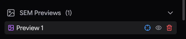
SEM Previews lists your preview grabs. Click the header to expand the list.
- Click a preview to select it. Samurai then draws it on top, at full strength. Click it again to deselect it. Unselected previews are drawn at half strength, so they never hide your data.
- centres the viewport on the preview. The eye hides or shows it.
- Click , then ✓. Samurai deletes it permanently from disk.
Tiles Previews lists the captures you made with the camera buttons in the ROI panel. A capture can be a single tile or a whole ROI (Section 12.6). Click a capture to select the tiles it covers. This also shows the capture at full strength. Autofocus Images lists the reference images taken after each built-in autofocus.
11.3 Pixel size, field of view and image size
Three numbers describe every image. If you choose any two, the third follows:
field of view = image width in pixels × pixel size
For example, 2048 pixels at 10 nm give an image 20.48 µm wide. If you double the pixels and keep the pixel size, the field doubles. If you keep the field and double the pixels, each pixel becomes half the size. Section 12.4 shows how this sets the size of your tiles. It also has a calculator.
11.4 Beam voltage and the depth you see
The beam voltage decides how deep the electrons go into the block. So it also decides how much of the material below the block face shows up in each image. For biological samples, 2–4 kV is typical.
| Higher kV | Lower kV |
|---|---|
| Stronger signal and a better signal-to-noise ratio | Weaker signal. You may need a longer dwell time or larger pixels. |
| Reaches deeper below the surface | More of the signal comes from the surface |
| More beam damage per cycle | Less damage |
The rule of thumb: when you cut thinner, lower the voltage. Sections of about 50–100 nm work well at around 3–4 kV. Sections of 30 nm or less usually need 1.5–2 kV, so that the beam stays within one section.
11.5 Dose, signal and cutting
Every image leaves electrons in the block. If the block gets too many, the resin softens and no longer cuts cleanly. The SEM panel shows the electron dose in e⁻/nm². It tells you how many electrons each square nanometre gets from a preview with the current settings:
dose = probe current × dwell time ÷ pixel area
Some examples of this balance:
- With a very low dose, below about 1 e⁻/nm², you can cut very thin sections, such as 15 nm. But the images become noisy, and the noise limits the resolution anyway.
- Several images per cut, a very high signal-to-noise ratio, or very small pixels may force you to cut thicker. For example, you may have to cut 100 nm sections to keep the cutting clean.
- A more sensitive backscatter detector gives the same signal from a lower dose, so you can cut thinner.
11.6 A good starting point
SBF-SEM (serial block-face SEM) has a "sweet spot" for a well-stained biological sample embedded in resin. In this range, it is easy to get good results:
| Setting | Starting value |
|---|---|
| Accelerating voltage | 2 kV |
| Electron dose at the sample | about 15 e⁻/nm² |
| Detector | a modern backscatter detector that gives a signal-to-noise ratio above 4 : 1 at these settings |
| Voxel size (the size of one 3D pixel) | 6–15 × 6–15 × 40–80 nm |
| Section thickness | 30–50 nm is typical. For most biological samples, about 25 nm is a practical limit, or 15 nm under very good conditions. Some materials, such as soft metals, can be cut cleanly even thinner. |
Then adjust:
- To cut thinner, lower the dose or the voltage, or use a more sensitive detector.
- If you need more signal or smaller pixels, cut thicker.
- If the block charges (a build-up of electrons that spoils the image) or is damaged, lower the dose or the voltage.
11.7 Knife oscillation
The knife oscillates (vibrates very fast) while it cuts. This improves the cut, and it can let you cut thinner sections. The best frequency depends on the sample. 5, 12 and 37 kHz are known to give good in-plane oscillation, where the knife vibrates within its own plane. Samurai offers them as presets. Samurai's default is 50 kHz with 50 % amplitude. Leave the oscillator on at a preset. Change the frequency or amplitude only if you see cutting artefacts.
You set the oscillator for an experiment in Microtome Settings in the Imaging tab (Section 15.1). The Approach tab has its own oscillator settings (Section 9.6).
Regions of interest and tiles
A region of interest (ROI) is an area of the block face that you want to image. Samurai fills each ROI with a grid of tiles. Each tile is one SEM image. An experiment can have several ROIs, and each ROI has its own image size, pixel size and timing.
12.1 The ROI panel
The ROIs panel in the right sidebar lists your ROIs. Below the list, you see ROI Settings for the selected ROI, or Tile Settings for the selected tiles.
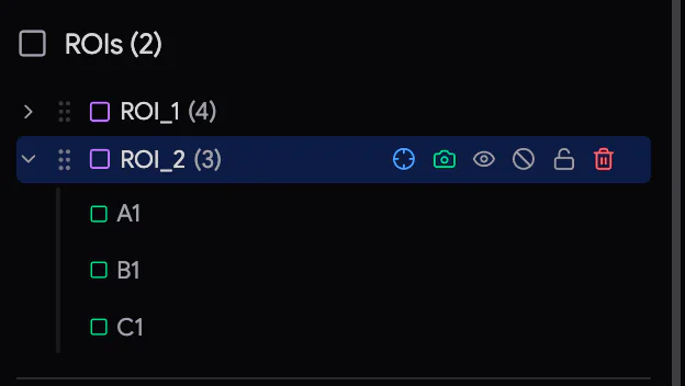 1234567
- ROI row — the chevron shows the ROI's tiles. The number is its tile count.
- Drag to reorder acquisition order.
- Center viewport on ROI and Capture ROI (all tiles).
- Eye — show or hide the ROI in the viewport. A hidden ROI is still imaged.
- — disable or enable all the ROI's tiles.
- — the ROI lock (Section 13.1). — delete the ROI.
- Tile rows — capture, AF (autofocus), reference marker and disable.
Most row buttons appear when you hover over the row. Click a row to select the ROI or tile. The viewport follows your selection.
When the pointer is not in a text field, you can use these keys:
- ↑ ↓ move through the list.
- → expands an ROI.
- ← collapses it.
In the tile list, Ctrl/⌘-click adds tiles to the selection or removes them. This works even across ROIs.
Once cycles (rounds of imaging and cutting) exist, the list shows each ROI with its cycle number in front, for example 12-ROI_1. The number tells you that the row belongs to the cycle you are looking at.
12.2 Draw an ROI
- Make sure an experiment is open and the microscope is connected. Take a preview, so you can see where to draw (Section 11.2).
- Press D, or click Draw ROI in the toolbar. The panel shows New ROI: the tile size, pixel size, dwell time and overlap that the next ROI will get. Change them if needed.
- Drag a rectangle over the area you want. To snap its corner and size to the visible grid, hold G.
- Release the mouse button. The new ROI appears with its tiles, and Samurai selects it. ROI Settings opens.
- The Draw tool stays active, so you can draw another ROI straight away. To go back to the Select tool, press V or click a row. Esc switches to the Hand tool.
- An ROI smaller than one tile grows to one whole tile.
- If an ROI has more than 1,000 tiles, Samurai asks you to confirm (Large Tile Count). Samurai does not allow grids of more than 10,000 tiles.
- ROIs are named ROI_1, ROI_2 and so on.
- For a very large ROI, a Generating tiles... panel with Cancel appears briefly.
If cycles already exist, Samurai adds the new ROI to every cycle. In the cycles before the current one, it is created disabled. So the new ROI is only imaged from now on.
12.3 ROI Settings
Select an ROI to see its settings. To change a blue value, click it and type a new one. Press Enter to confirm or Esc to cancel. Or choose a new value from its drop-down.
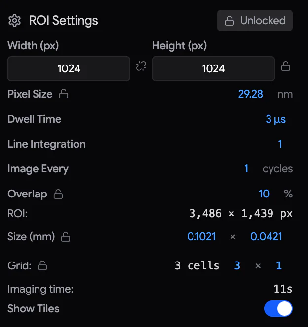
| Setting | What it means |
|---|---|
| Width (px) / Height (px) or Image size (px) | The size of each tile image in pixels. If your microscope has fixed sizes, you choose from a list. |
| Pixel Size | The size of one pixel on the sample, in nm. |
| Dwell Time, Frame Time or Scan Mode | How long each pixel (or each frame) is exposed. Which one you see depends on your microscope. If you change it here, it changes for every tile of the ROI. |
| Line Integration | How many times each line is scanned and averaged. A higher number gives less noise but takes more time. |
| Image Every | Image this ROI only every N cycles: on cycles 1, 1+N, 1+2N… |
| Overlap | How much neighbouring tiles overlap, in %. Positive values make the tiles overlap, up to 40 %. Negative values leave gaps. |
| ROI: | The ROI's size in pixels (read-only). |
| Size (mm) | The ROI's width and height. |
| Grid: | The number of tiles, and how many across × down. You can type the counts. |
| Imaging time: | The estimated time for one visit to the ROI. It is the scan time of its enabled tiles plus stage travel. Autofocus is not included. |
| Show Tiles | Use it to hide the tiles in the viewport, so you can see the image underneath. |
If you change the image size, pixel size, overlap or ROI size, Samurai rebuilds the tile grid. Disabled tiles and per-tile dwell times are kept. Samurai matches them by tile name.
Once cycles exist, a change applies from the current cycle to the end of the run. If you are looking at a future cycle, the change starts there instead (Section 14.3). You cannot change past cycles.
12.4 Tile size, overlap and the grid
The size of a tile on the sample is its pixel count times its pixel size. Neighbouring tiles are placed one step apart. The step is the tile size reduced by the overlap:
- tile width = width in pixels × pixel size
- step = tile width × (1 − overlap)
- tiles across = the largest whole number of tiles that fits inside the ROI
The grid starts at the top-left corner of the ROI. Samurai keeps only whole tiles that fit completely inside the ROI. So if your ROI is a little larger than a whole number of tiles, a thin unimaged strip remains along its right or bottom edge. This is on purpose: your ROI keeps the size you drew. If you need that strip, make the ROI slightly larger or change the overlap.
Tiles are named by column letter and row number. The top row is A1, B1, C1 …, then the next row starts at A2 …, and so on. In wide grids, the column letters continue Z, AA, AB …. Within an ROI, Samurai images the tiles in this order, row by row.
12.5 Working with tiles
Enable and disable tiles
Disable the tiles you do not need, such as empty resin or damaged areas. This saves time and beam dose. Acquisition, ROI captures and EDS all skip a disabled tile. A disabled tile is drawn with a dashed orange outline.
| To disable… | Do this |
|---|---|
| One tile | Hover over its row and click Disable tile. Click again to enable it. |
| Several tiles | Select them in the list or in the viewport (Section 8.3). Then switch on Disable Selected Tiles in Tile Settings. |
| A whole ROI | Click on the ROI row. |
Once cycles exist, the change applies from the current cycle onwards. If you are viewing a future cycle, it applies from that cycle. For example, you can disable a damaged area from cycle 50 and enable it again from cycle 60 (Section 14.3). You can disable and enable tiles during a run, and also on a locked ROI.
Tile Settings
Select one or more tiles to see Tile Settings:
- Dwell Time or Frame Time — a dwell for the selected tiles only. It is used instead of the ROI's value until you change the ROI's dwell again.
- For a single tile: its Pixel size, Electron dose, Size and Imaging time. The dose appears only on microscopes that report the probe current.
- Disable Tile / Disable Selected Tiles.
- Auto Focus / Auto Focus Selected — mark the tiles for autofocus.
Autofocus tiles
To use a tile for autofocus, click the AF chip on its row, or switch on Auto Focus in Tile Settings. The chip turns cyan. Choose tiles with sharp, high-contrast structure, and avoid empty resin. Autofocus tiles have a cyan outline in the viewport. Chapter 17, Autofocus and autostigmation explains the methods.
Reference tiles
The moon/sun marker on a tile row marks a reference tile for image corrections. Each click changes the marker to the next state: none → dark reference → bright reference → none.
- The dark reference (moon) is captured with the beam blanked.
- The bright reference (sun) is used to measure image drift.
Use two different tiles for the dark and the bright reference. Section 16.4 explains what they are used for.
12.6 Capture a tile or an ROI now
The camera buttons take images at once, outside a run. Use them, for example, to check focus and settings before you start, or to image a region once.
- on a tile row captures that tile.
- on an ROI row is Capture ROI (all tiles). It captures every enabled tile of the ROI, in order. If some of the ROI's tiles are selected, it captures only those.
Samurai drives the stage to each tile. If a move is longer than 10 mm, Samurai asks you to confirm it first. If Imaging Addition is on, Samurai raises the stage for imaging. Each image appears in its place in the viewport. While Samurai works, the camera button turns into a spinning icon and a red ✕. Click the ✕ to cancel.
The captures are listed under Tiles Previews in the SEM panel (Section 11.2). They are previews, not part of the cycle data.
You cannot use the camera buttons:
- during a run
- while another image is being taken
- while you are looking at another cycle in Time Travel
12.7 Several ROIs
- Acquisition order follows the list, from top to bottom. To change it, drag the grip. A line shows where the ROI will go.
- Drawing order in the viewport is a separate choice. Where ROIs overlap, the arrow next to ROIs in the Overlays list decides which one is drawn on top. Your clicks also go to the ROI on top. The drawing order does not change the acquisition order.
- Different settings per ROI. Each ROI has its own image size, pixel size, timing, overlap, Image Every interval, autofocus tiles and disabled tiles. For example, you can image a large overview ROI every 10 cycles with large pixels, and a small detailed ROI every cycle.
12.8 Delete an ROI
Hover over the ROI row and click . Then click the red ✓ to confirm, or click anywhere else to cancel. Samurai removes the ROI from every cycle. Images already saved on disk are kept.
You cannot delete an ROI while a run is in progress. You also cannot delete a locked ROI ("Unlock this ROI before deleting it"). To undo a deletion, press Ctrl/⌘+Z. If you only want to stop imaging an ROI, disable its tiles instead.
Locking ROI geometry
Once an ROI has images, its position and grid must not change by accident. If they did, new images would no longer line up with the old ones. And while you set up an ROI, you often want to fix one thing, such as a 3 × 3 grid. Samurai then works out the rest. For these two jobs, Samurai has two kinds of lock.
| The ROI lock | Parameter locks | |
|---|---|---|
| What it is | One padlock per ROI. You find it on the ROI's row, and as the Locked / Unlocked chip in ROI Settings. | Six small padlocks next to the settings in ROI Settings |
| What it does | Freezes the ROI. You cannot move, resize or delete it, or change its geometry. | Keeps one value fixed while you change others |
| Typical use | Protect an ROI that already has images | Keep a 3 × 3 grid, or a 10 nm pixel size, while you adjust the rest |
13.1 The ROI lock
To lock or unlock an ROI, click the padlock on its row. You can also use the Locked / Unlocked chip at the top of ROI Settings. A locked ROI shows an amber padlock.
You cannot move, resize or delete a locked ROI. You also cannot change its image size, pixel size, scan mode, overlap, size or grid. Undo cannot change it either.
You can still:
- rename it, hide or show it, and reorder it
- disable tiles, and mark autofocus and reference tiles
- change its dwell time, frame time, line integration and Image Every
- capture it, and of course image it
Samurai locks ROIs by itself at two moments:
- When you generate cycles for the first time (Section 14.1). Samurai then locks every ROI.
- When a manual capture produces an image of the ROI (Section 12.6).
Separately, Samurai freezes the geometry of every ROI while a run is in progress. This happens whatever the ROI's lock says.
13.2 Parameter locks
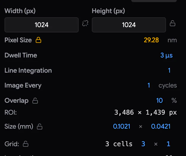
You can lock six settings:
| Lock | Next to | Keeps fixed |
|---|---|---|
| Pixel size | Pixel Size | The pixel size |
| Resolution | Width/Height or Image size | The image size in pixels |
| Aspect ratio | between Width and Height | The width-to-height ratio |
| Tile count | Grid | The number of tiles across and down |
| ROI size | Size (mm) | The ROI's width and height |
| Overlap | Overlap | The overlap between tiles |
Locks are hard. When you change one setting, other unlocked settings adjust so that everything still fits together. But sometimes your change could only work by breaking a lock. Then Samurai makes no change at all. A notice, Change blocked by a lock, names the locks in the way, and they flash red. The deepest red marks the lock you would have to unlock first. Nothing is saved until the change is possible.
Target and actual. When you lock a value, Samurai remembers it as a target. Some microscopes cannot deliver every value exactly, for example a microscope with fixed magnification steps. If the delivered value differs from your target, the padlock's tooltip shows both values. The padlock then has three states:
- Locked at your target.
- Click once: re-lock at the value the microscope delivers.
- Click again: unlocked.
If you type a new value into a locked field, the lock's target moves to the new value.
13.3 Which setting gives way
When you change one setting, several unlocked settings may be able to adjust to fit it. Samurai then uses a priority list to decide which one moves: Settings › Advanced › ROI Lock Priority.
- The item at the bottom gives way first.
- The item at the top is kept the longest.
- Locked items never move.
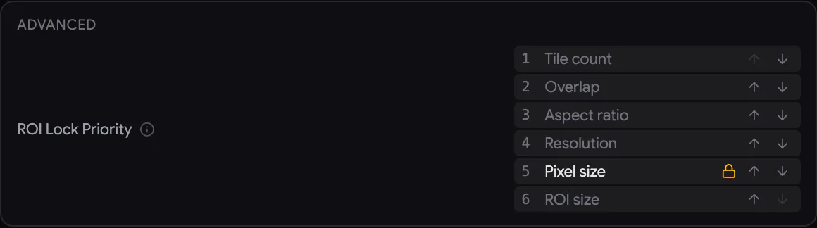
The default order, from the most protected to the first to give way:
- Tile count
- Overlap
- Aspect ratio
- Resolution
- Pixel size
- ROI size
Some microscopes, such as JEOL, do not let Samurai set the resolution. On these microscopes, Resolution starts at the top. Samurai remembers the order and the locks for each microscope.
Some typical cases:
- Change the width, nothing locked: the field of view stays the same, so the pixel size changes.
- Pixel size locked: changing the width changes the field of view instead.
- Aspect locked: if you change the width or the height, the other one changes too, to keep the ratio.
- Tile count locked: if you change the overlap, resolution or pixel size, Samurai resizes the ROI so that the tiles fit exactly. It does not change your pixel size instead.
- Typing a new ROI size takes priority over the list. The ROI goes to the size you typed. If the tile count is locked, it goes to the nearest size that fits exactly.
Locks for ROI size, tile count, overlap and resolution follow the ROI you select. When you select another ROI, these locks take their targets from that ROI. A pixel-size lock keeps its target when you select another ROI.
13.4 Pixel-size helpers
- ‹ › arrows appear next to the pixel size when only certain pixel sizes are possible. This happens on microscopes with fixed magnifications, or when the ROI size and overlap are both locked. Each click moves to the next possible value.
- A small badge after the value tells you what happened to your entry:
- snapped: moved to the nearest value the microscope can deliver.
- CLAMPED: limited to the end of the possible range.
- source: this microscope does not let Samurai set the field of view. The pixel size only records what the microscope delivers.
- Some microscopes do not let Samurai set the resolution. If Samurai changes the resolution on such a microscope, an amber note asks you to Update the SEM resolution manually. Set the new size on the microscope PC.
13.5 Grow an ROI without moving its tiles
Sometimes a feature appears at the edge of the block partway through a run. You want to extend the ROI to include it, without disturbing the tiles you have already imaged. You do this by dragging a corner of the ROI.
- Select the ROI with the Select tool. A blue handle appears at its bottom-right corner. Once cycles exist, a violet handle also appears at its top-left corner.
- Drag a handle to add or remove whole rows and columns of tiles. The tile size, pixel size and overlap stay exactly as they were. So does every existing tile, with its name and position.
- You cannot shrink the ROI past tile A1.
- Columns added on the left are named XA, XB, …. Rows added above are numbered 0, −1, …, for example
XA-1. This way, the original tiles keep their names. - You can drag only the corners, not the edges.
If ROI size is locked, Samurai refuses the drag, and the Size row flashes. If Tile count is locked, the lock takes the new count as its target. A locked ROI shows no handles, so unlock it first.
Cycles and Time Travel
A cycle is one round of the serial block-face process. First, Samurai images the block face: every enabled tile of every ROI. Then it cuts a section away to expose the next face. Cycle 1 images the surface you prepared during the approach.
You plan an experiment as a number of cycles. Every cycle keeps its own copy of the ROIs, tiles and microtome settings. So you can plan changes for the future and look back at the past.
14.1 Generate cycles
When your ROIs are ready, create the cycles:
- In the left sidebar, click the Total Cycles number. Type how many cycles you want. You can add more later.
- Click the purple Generate Cycles button next to it. Its tooltip says Generate N cycles.
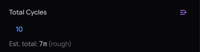
Samurai then:
- creates one cycle per section, each with the current microtome settings and a predicted Z height
- copies every ROI and tile into every cycle
- locks every ROI, so that its geometry cannot change by accident (Section 13.1)
- shows the Time Travel control at the top of the right sidebar
- replaces the Generate button with Start
You need at least one enabled tile. After generation, you can still change Total Cycles:
- A larger number adds cycles at the end, even during a run.
- A smaller number removes cycles from the end. It never removes a cycle that has started.
14.2 Time Travel
Time Travel lets you look at any cycle: past, present or future. The run itself always continues at the live cycle (the cycle the run is on, or will start with). Time Travel only changes what you see, and the cycle your edits start from.
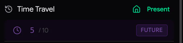
| To | Do this |
|---|---|
| Step one cycle | Scroll over the control: up for later, down for earlier. To move 10 cycles per step, hold Ctrl/⌘. |
| Move quickly through the cycles | Drag the clock icon left or right. For fine steps, hold Shift. |
| Go to a cycle | Click the number, type the cycle and press Enter. |
| Go to the first or last cycle | Click the control, then press Home or End. |
| Go back to now | Click the green Present button. |
While you look at another cycle:
- The control is blue with PAST for a past cycle. It is purple with FUTURE for a future cycle.
- The viewport has a sepia (brown) frame for a past cycle, and a purple frame for a future cycle.
- The viewport shows that cycle's tiles and images.
- Microtome Settings show that cycle's values, with (Cycle N) next to the heading.
Each step makes a small click sound. To turn it off, use Settings › General › Time Travel Click Sound.
14.3 What changes where
Changes never rewrite the past. They apply forward, from a starting cycle to the end of the run:
| You change… | It applies from… |
|---|---|
| Microtome settings (thickness, cut speed, clearance, oscillator) | the future cycle you are looking at, otherwise the live cycle |
| ROI settings (pixel size, image size, overlap, dwell…) | the future cycle you are looking at, otherwise the live cycle |
| Enabled/disabled tiles | the future cycle you are looking at, otherwise the live cycle |
| Resizing an ROI with a corner handle | the cycle you are looking at |
| Moving an ROI | always the live cycle, whichever cycle you are looking at. An ROI's position is a physical place on the block. |
| A new ROI | every cycle. It is disabled in cycles before the live one. |
| Gating Sync, which applies a mask's choice of tiles to skip (Section 21.7) | the live cycle |
| Anything while looking at a past cycle | nothing. Past cycles are read-only. |
A temporary change needs two edits. For example, to skip a damaged area for ten cycles:
- Go to cycle 50 and disable the tiles over the damage.
- Go to cycle 60 and enable them again.
Check both cycles afterwards. If you later make an edit that starts earlier, say at cycle 40, it writes forward again. It then replaces both of your edits.
14.4 Undo and redo
Samurai keeps a history of your edits in the Imaging tab. To undo, press Ctrl/⌘+Z. To redo, press Ctrl/⌘+Shift+Z or Ctrl/⌘+Y.
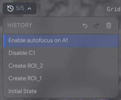
The History button in the top-left corner of the viewport shows where you are in the history, for example 7/12. Click it to see the list, newest first. Click any entry to step back to it, or forward again. Clear history makes the current state the new starting point.
What is recorded:
- creating, deleting, moving and resizing ROIs
- ROI settings, visibility, locking and reordering
- enabling and disabling tiles
- autofocus and reference marks
- per-tile dwell
- mask and reference edits, and keyframes
What is not recorded:
- microtome settings
- generating cycles
- starting, stopping and skipping
- creating or deleting a mask
- gating Sync
- hardware and acquisition settings
- pan, zoom and selection
Good to know:
- Samurai carries out an undo as a new edit. So it follows the rules that apply now. For example, undoing an ROI move moves the ROI again, from the live cycle.
- Undo and redo cannot change a locked ROI or mask either. The step fails with a message such as ROI_1 is locked. Unlock it to change it. The history stays where it was.
- Undo cannot reverse the imaging of a tile or the cutting of a section.
- When you open another experiment, Samurai starts a new, empty history. Studio has its own history.
Running an acquisition
This chapter covers the controls in the left sidebar of the Imaging tab. Use them to set the microtome for the run, and to start, watch, stop and resume it.
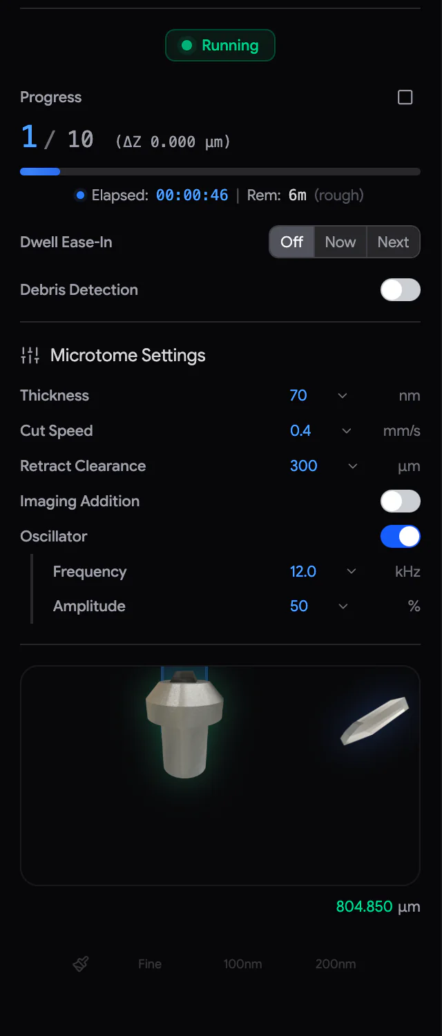 12345
12345- Status — Running, Stopping…, Stopped or Completed.
- Progress — the current cycle and the total, the Z of the cutting plane (ΔZ), the time elapsed and remaining, and the Stop button.
- Dwell Ease-In and Debris Detection.
- Microtome Settings — thickness, cut speed, retract clearance, Imaging Addition and oscillator.
- Position display — the knife and sample, the live Z, Sweep and the quick-approach buttons.
While a cycle runs, the Now / Tile / Next box under the progress bar shows what Samurai is doing and what comes next. Click its chevron to see the full list of actions.
15.1 Microtome settings for the run
Microtome Settings hold the cutting settings for the cycles of this experiment. They are separate from the values on the Approach tab.
| Setting | Presets | Default | What it does |
|---|---|---|---|
| Thickness | 25, 30, 40, 50, 70 nm | 50 nm | The section thickness. The stage rises this much before each cut. You can set 1–200 nm. |
| Cut Speed | 0.05 – 2 mm/s | 0.2 mm/s | How fast the knife crosses the cutting window, the part of its path over the block. Slower cuts are cleaner. |
| Retract Clearance | 100, 300, 500 µm, Max | 300 µm | How far the stage drops before the knife returns (Section 9.6). |
| Imaging Addition | 300, 500, 700 µm | off | Raises the sample for imaging and lowers it for cutting (Section 15.2). |
| Oscillator | 5, 12, 37 kHz · 20, 50, 100 % | on, 50 kHz, 50 % | How fast and how strongly the knife vibrates during cuts (Section 11.7). |
You can change the thickness, cut speed, clearance and oscillator during a run. The new values apply to the cycles still to come. If you change the thickness, Samurai re-plans the Z height of every remaining cycle. It then shows the target of the next cut (Next outgoing cut: +… nm). If you use Time Travel to look at a future cycle, the heading shows (Cycle N). Your change then starts at that cycle.
Under the settings, the position display shows the knife over the cutting window, the sample pin and the live Z. Its buttons act at once:
- Sweep makes one knife pass forward and back, without raising the stage. Use it to clear debris from the block face.
- Fine, 100nm and 200nm are quick-approach buttons. Each click adds one full approach cycle to a queue: raise, cut, drop, return. Fine uses the thickness and cut speed from Microtome Settings. 100nm cuts 100 nm at 1 mm/s. 200nm cuts 200 nm at 2 mm/s. The button shows how many cycles are waiting (×N). The red ✕ cancels the rest.
You cannot use these buttons during a run or while the stage is raised.
15.2 Imaging Addition
On some microscopes, the best height for imaging is not the cutting height. Imaging Addition raises the sample by a set amount before each cycle's imaging. This puts the block face at the SEM's focus. Before the cut, Samurai lowers the sample back to the cutting plane, the height at which the knife cuts.
To use it, switch on Imaging Addition and set the amount (1–1300 µm). Focus Position, above the position display, then shows the imaging height. If the stage will reach its 1300 µm limit before the run ends, a small icon next to the amount warns you. The icon also tells you how many cycles still fit.
Raise Stage to Focus is the arrow button beside the amount. It lifts the stage to the focus position now, for example so you can focus the microscope by hand. The knife retracts first. While the stage is raised:
- A pulsing blue banner, STAGE RAISED TO FOCUS, runs across the top of the viewport.
- Most controls in the left sidebar are covered, and the Approach tab is locked.
- The arrow button becomes Lower Stage to Cutting Plane.
If a run stopped while the stage was raised, you can resume it as it is. The run continues imaging at the raised height, and lowers the stage before the next cut.
15.3 Dwell Ease-In
A freshly cut surface is most sensitive to the beam. Dwell Ease-In starts with a short dwell time and increases it step by step (a ramp) until it reaches the ROI's full dwell. Cycles sets how many cycles the ramp takes (default 10). With 10 cycles, the dwell goes 10 %, 20 %, … 100 %.
| Choice | Effect |
|---|---|
| Off | Every cycle images at the full dwell time. |
| Now | The ramp starts with the next image. |
| Next | This cycle still images at full dwell. The ramp starts with the next cycle. |
If Now or Next is selected, Samurai sets up the ramp again every time you press Start or Resume. When the ramp is done, switch it back to Off, unless you want it to restart after each resume. Ease-In is only offered on microscopes that use a dwell time.
15.4 Before you start
- The approach is complete, and the stage is at the cutting plane (not raised).
- The microscope is connected, focused and stigmated. Its beam and detector are ready.
- ROIs, pixel sizes, dwell times and overlap are right. Tiles you do not want are disabled.
- Cycles are generated, with enough cycles and a sensible thickness.
- Autofocus, debris detection, EDS, scripts and mask gating are set up as you want. Mask gating (skipping the tiles a mask does not cover) is synced.
- If you use the PCN gas needle, its mode and position are right (Chapter 20, The PCN needle).
- There is enough free disk space for the images.
15.5 Start
Click Start. The button's tooltip says what it will do: Start, Resume or Continue (new cycles appended). If the button is disabled, the tooltip says why. For example: Generate cycles first, Microtome not connected or SEM is disconnected. Reconnect the matching SEM to continue.
Before the first image, Samurai checks that it is safe to begin. You may see:
| Message | Meaning |
|---|---|
| Microtome Z Position at Zero | Z is exactly 0 µm. This is unusual after an approach. Continue only if you are sure the sample is at the cutting plane. |
| Microtome Z Position Changed | The stage is not where the plan expects, for example because you cut more on the Approach tab. Continue changes the planned Z of the remaining cycles to match. |
| Resume Z Mismatch | The Z of the interrupted cycle no longer matches. Z Resync images this cycle again at the current height and re-plans the rest. |
| Very Long Tile Acquisition | One tile would take over 5 minutes. Check that the dwell time units are right. |
| Cannot start acquisition: stage is at an elevated imaging position | Lower the stage first (Section 15.2). |
| Imaging addition exceeds the stage limit | Reduce the addition or switch it off. |
| Needle could not be parked before the run | The PCN could not park its needle. See Section 20.10. The notice has a Clear PCN fault button. |
| The previous cut has no completion record | Samurai cannot confirm that the last cut finished. Check the block face and Z. Then click Clear cut record and start again. |
The status then shows Starting.... The run begins at the next unfinished cycle, no matter which cycle Time Travel shows.
15.6 What happens in each cycle
- Raise the stage to the focus position, if Imaging Addition is on.
- Autofocus, if it is due (Chapter 17, Autofocus and autostigmation).
- Image every enabled tile: ROI by ROI in list order, and tile by tile. After each tile, Samurai may check it for debris (Chapter 18, Debris detection). It may also adjust the detector brightness (Section 19.3) and collect a scheduled EDS map (Chapter 22, EDS maps with Oxford AZtec).
- Retry the tiles that failed in this cycle, once.
- Lower the stage to the cutting plane and run the before-cut scripts.
- Park the PCN needle, if one is fitted, and cut one section.
- Run the after-cut scripts and start the next cycle.
On the very first cycle, the after-cut scripts also run once at the start. This makes sure scripted equipment is ready for the first image.
15.7 Watch the run
- Progress shows the cycle (for example 12 / 400) and the Z of that cycle's cutting plane (ΔZ). It also shows the Elapsed and Rem (remaining) time. Before a run, the time estimate is marked rough. It gets better after a few measured cycles.
- Now says what is happening, for example Imaging ROI_1 - B2, Cutting at 102.350 µm or Autofocus. Tile shows the progress through this cycle's tiles. Next says what comes next.
- Click the chevron to open the action list. It shows every ROI with its tile count (done/total), the tiles with their status, and the cut.
- In the viewport, the tile being imaged pulses green. A line along its bottom shows the exposure. A blue line shows that the image is being stored (Section 8.7).
- The Warnings and Errors tabs of the console collect anything worth your attention.
15.8 Stop
There is no pause button. You can always resume after a stop. You also choose how far the run goes before it stops.
- Left-click Stop to stop after the current image.
- Right-click it for more choices:
| Choice | The run… |
|---|---|
| Stop immediately | cancels the SEM scan in progress. This works only on microscopes that can interrupt a scan. The unfinished tile is imaged again when you resume. |
| Stop after this image | finishes the current tile. |
| Stop after this ROI | finishes the tiles of the current ROI. |
| Stop at end of this cycle | finishes all the images of this cycle and its before-cut scripts. It stops before the cut. The cut happens when you resume. |
| Cancel stop — keep running | cancels a stop that has not taken effect yet. |
While the run is stopping, the status shows, for example, Stopping after this ROI.... You can move a pending stop earlier, for example from end of this cycle to after this image. You cannot move it later. If you press Stop while the cut or the scripts just before or after it are running, that step finishes first. A cut is never interrupted. After a stop, the status is Stopped. If Imaging Addition is on, the stage may stay raised.
15.9 Skip and re-acquire
In the action list, the skip icons skip pending work in the current cycle. You can skip all tiles of the cycle, all tiles of one ROI, or a single tile. Click the icon again to unskip. If you skip every tile, the run moves on to the cut. Skips apply only to the live cycle, the one the run is on. They do not disable tiles.
If a tile of the current cycle has a partial or bad image, you can image it again. Right-click the tile in the viewport and choose Re-acquire in This Cycle. Samurai images it again after the tile in progress, or when you resume. Samurai refuses for a completed cycle, a disabled tile, or the tile being imaged right now. It tells you why.
A tile fails when, for example, no image arrives in time, the connection is lost, or the stage does not arrive. Samurai then retries the tile as set in Settings › Advanced › SEM Failed Action Retries. If the tile still fails, Samurai flashes it red, tells you and carries on. At the end of the cycle, it tries the failed tiles once more. Settings › Imaging › Max Sequential Failed Tiles Allowed stops the run when too many tiles fail in a row. By default, the first failure stops it. If Min Standard Deviation is on, a blank tile also counts as a failed tile (Section 16.3).
15.10 Resume
After a stop, click Resume. The run continues exactly where it stopped, at the same cycle and the same step. It images any unfinished tiles again.
If Samurai stopped the run by itself, the console says why (Imaging paused during cycle N: …). Fix the cause, then Resume. Common reasons:
| Reason | What to do |
|---|---|
| Stage Z is … but cycle N expects … | The stage was moved, or the sample height changed. Nothing was moved automatically. Use Z Resync at the next Start, or move Z back. |
| Stage Z stayed … from the plane after … correction moves / The Katana did not hold the plane | The microtome did not settle at the right height. Check the controller, cable and sample, then Resume. |
| The disk is full | Free up space on the named drive. The unsaved tile is imaged again. |
| SEM unavailable | The microscope could not image (interlock, vacuum, beam off). Fix it on the microscope, then Resume. |
| Image store failed | The image could not be stored. Samurai saved it in the experiment's recovery folder and will add it to the image store automatically. Check the disk, then Resume. |
| Too many sequential failed tiles | Check the microscope and stage. The tile is imaged again when you resume. |
If Samurai was closed or crashed during a run, the experiment reopens with the run Stopped. A console note names the last finished tile. Check the stage position, and the Stage Position Warning if it appears. Then Resume.
15.11 When the run completes
The status shows ✓ Completed N/N cycles. To continue cutting and imaging, raise Total Cycles. The button then becomes Continue (new cycles appended). If Settings › Imaging › Beam Off on Complete is on, Samurai switches the beam off when the run completes.
Image display and quality checks
How an image looks on screen and what was recorded are two different things. This chapter covers the display controls, which never change your data. It also covers the checks Samurai makes on every image during a run.
16.1 Display levels: the histogram
The Histogram panel, at the bottom left of the viewport, sets the black and white points of the display. To show or hide it, click in the toolbar. To collapse it to one line, click its chevron.
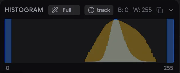
- One setting for the whole viewport. The black and white points apply to every acquired image on screen. They also apply to the second viewport window.
- What it measures. The histogram shows the selected tiles or the selected ROI. If nothing is selected, it shows everything on screen. To judge the levels, select a typical tile. The result applies everywhere.
- Drag the handles to set the black and white points by hand. You can also drag near a line on the graph. B and W show their values (0–255).
- Auto clips a small share of the darkest and brightest pixels, so they show as pure black or white. Each left-click moves to the next step: Fit (the exact data range), 0.0001 %, 0.001 %, 0.01 %, 0.1 %, 1 %, 2 %, 5 %, and then back to Full (0–255). Right-click goes back one step.
- track applies the current Auto level again whenever the histogram content changes. This happens with a new cycle, a new selection or new tiles arriving. The display then keeps up during a run.
- The copy icon copies the histogram values to the clipboard.
The levels are saved with the experiment.
16.2 Flat-field correction for display
Large tiles are often darker, or lower in contrast, towards their edges. Samurai can even this out on screen with a flat-field correction. It uses two correction images, called fields: one for brightness and one for contrast. The stored images do not change.
With the experiment open, set it up in Settings › Imaging › Image correction:
- Click ⚙ Generate from experiment… to open the Flat-Field Wizard. Choose an ROI, a range of cycles, and a method for each field. Click ⚙ Generate fields. Check the corrected preview of the centre tile, then click Apply to experiment.
- Or click Load brightness / Load contrast to use field images (PNG) made elsewhere.
- Set the mode to Flatfield. Each field has a Correction multiplier (0–200 %). It sets how strongly that field is applied.
The same Original / Flatfield choice is in the viewport's Overlays list (Section 8.8). Each experiment has its own correction.
16.3 Automatic checks during a run
Samurai checks every image it records:
| Check | Setting | What happens |
|---|---|---|
| Clipped pixels | Settings › Imaging › Image Quality Validation › Max Clipping Allowed (%) (5 %, on) | If more than this share of a tile is fully black or fully white, Samurai warns you once per cycle. For example: Tile 17-ROI_4-A1: 7.8 % clipped black. The run continues. Rebin before counting (2×2) averages small blocks of pixels first, so single noisy pixels are ignored. |
| Blank tiles | Min Standard Deviation (3, off) | When this is on, a tile whose pixel values hardly vary counts as a failed tile. This happens when the beam is blanked, the column valve is shut or the detector is off. A failed tile is not saved. It is imaged again at the end of the cycle, and it counts toward the limit in the next row. The value uses a 0–255 scale. Each tile's value is in its .md file (Frame Std (0-255)). Tiles over empty resin can be flat too, so check a few before you choose a value. |
| Failed tiles in a row | Max Sequential Failed Tiles Allowed (0) | The run stops when more tiles than this fail one after another. With 0, the first failure stops the run. |
| Detector settings changed | — | Some microscopes (TESCAN) report the detector gain and black level. On these, the first tile of a run records them. If they change during the run, Samurai warns you. It also notes the change in the metadata of every affected image. |
| Microscope cannot image | — | If the microscope reports that it cannot image (an interlock, venting, the beam off), the run pauses before cutting. Samurai tells you why. Resume when it is fixed. |
| Needle disturbed | — | If a PCN gas needle is fitted and its movement disturbed a tile's exposure, the log names that tile. The image is kept (Chapter 20, The PCN needle). |
16.4 Reference tiles: brightness and drift
Two kinds of reference tile help you follow slow changes during a long run. Mark them with the moon/sun marker on a tile row (Section 12.5):
- A dark reference (moon) is imaged every cycle with the beam blanked. It records the detector's dark level, so you can see changes in the detector's offset.
- A bright reference (sun) is imaged at a fixed position every cycle. Samurai uses it to measure how far the image drifts. Settings › Advanced › Image Drift Warning (1000 nm) sets a distance. If the drift is larger, Samurai warns you in the console. This only measures. Nothing is corrected automatically.
If you mark one kind, also mark the other, on a different tile. Samurai refuses to start with only one. The metadata of each reference image records its type. To correct drift and brightness automatically, see Chapter 19, Correcting drift and brightness.
16.5 Metadata and temperature
Each recorded image has a small text file (.md) in the experiment's metadata folder. It holds everything known about the image:
- when it was acquired
- the microscope settings (voltage, current, working distance, field of view, dwell)
- the stage position and the pixel size
- the cycle and the tile
- any warnings
Temperature logging adds the room temperature. Switch on Settings › Advanced › Temperature Logging. Then enter the address of your temperature-logger service in Temperature Source URL. Samurai then records the temperature in each image's metadata. It also writes one line per cycle to temperature-log.csv in the experiment folder. Samurai never records a reading that is too old. Comparing the temperature with focus and drift can help you find the cause of slow changes.
Autofocus and autostigmation
During a run that lasts days, the focus drifts. The sample charges, the temperature changes, and the block surface slowly moves. Autofocus corrects the working distance (WD) during the run, and autostigmation corrects astigmatism. Together they keep the last images as sharp as the first.
17.1 Choose a method
The Autofocus panel in the right sidebar sets the method. The method applies to all experiments on this PC.
| Method | How it works | Best for |
|---|---|---|
| Off | No focus correction. | Short runs, stable samples. |
| SEM Built-in | Every N cycles, Samurai moves to each autofocus tile and runs the microscope's own autofocus routine. | Microscopes with a reliable autofocus. Only offered if your microscope has one. |
| Heuristic | Samurai sets the WD slightly higher on one cycle and slightly lower on the next. It measures the sharpness of the normal tile images and corrects the WD step by step. No extra images. | Long runs where focus drifts slowly. |
If your microscope lets Samurai set the stigmators, you can switch on Auto Stig to correct astigmatism too.
17.2 Mark autofocus tiles
Both methods work on the tiles you mark for autofocus. To mark a tile, click the AF chip on its row, or switch on Auto Focus in Tile Settings (Section 12.5). Marked tiles have a cyan outline.
Choose tiles with sharp, high-contrast structure, such as membranes or resin boundaries. Avoid tiles that are mostly empty resin. A good choice is a small ROI, away from your area of interest, that you use only for autofocus. The extra beam dose then falls outside the data you want (Section 12.7).
17.3 SEM Built-in
Set Every N cycles in the panel (default 10). On those cycles, before imaging, Samurai drives to each autofocus tile and runs the microscope's autofocus. From cycle 5 onwards, autostigmation runs on the same cycles. Samurai records the working distance before and after.
If the routine fails, Samurai discards the result and restores the previous focus. It does the same if the routine moves the WD by more than Max Correction (Settings › Imaging › Heuristic Autofocus, 0.002 mm). After each autofocus, Samurai takes a reference image. You find it under Autofocus Images in the SEM panel.
17.4 Heuristic autofocus
Heuristic autofocus needs no extra images. On one cycle, it images with the WD slightly above its current estimate of the best WD. On the next, it images slightly below. It compares how sharp the images are. Then it moves the WD a little towards the sharper side.
- A correction is applied every 2 cycles. If Auto Stig is on, the pattern takes 6 cycles: working distance, then stigmation X, then stigmation Y.
- Tracking decides which tiles are measured and corrected:
| Tracking | Behaviour |
|---|---|
| AF tiles only | Each autofocus tile gets its own correction. Other tiles use the average. |
| All tiles (individual) | Every tile is measured and corrected on its own. No marking needed. |
| Average AF corrections | The autofocus tiles are measured. One average correction applies to all tiles. |
| Global spatial fit | The autofocus tiles are measured. Samurai fits a flat plane through their corrections, so each tile gets a correction for its position. |
Reset Reference tells heuristic autofocus that you have just focused and stigmated by hand. It takes the current WD and stigmation as the new starting point. It also clears the correction history for the current and future cycles. Past cycles are kept. Use it whenever you refocus by hand during a run.
17.5 Watch it work
During a run, the left sidebar shows an Autofocus line with the tile being focused. The line also has a skip icon: Skip remaining autofocus for this cycle. Tiles being focused pulse cyan.
To open the Heuristic Autofocus Metrics window, click View Metrics in the Autofocus panel:
| Tab | Shows |
|---|---|
| Working Distance | The WD used for each autofocus tile, cycle by cycle. |
| Focus Estimators | All sharpness measures. Higher is sharper. |
| Corrections | The correction applied each cycle, with the limits. |
| Gradients | The measured slope. A positive value means the WD needs to increase. |
| Stigmation | Stigmation X and Y per tile. |
Scroll over a chart to zoom its values. Drag across it to select a range of cycles. Export CSV saves the data.
17.6 Tuning the heuristic
The settings for heuristic autofocus are in Settings › Imaging › Heuristic Autofocus. The defaults work for most samples.
| Setting | Default | What it does |
|---|---|---|
| Max Correction (mm) | 0.002 | The largest WD change applied in one step. Larger corrections are rejected. This also applies to SEM Built-in. |
| WD Perturbation (mm) | 0.0005 | How far the WD is moved up and down (δ). |
| Proportional Gain (Kp) | 1000 | How strongly the measured slope is turned into a correction. |
| Outlier Rejection | 0 (off) | Ignores images that are much less sharp than recent ones. Typical: 3. Cautious: 5. |
| Chase Mode | off | When focus stays far off in the same direction, it makes corrections larger for a while. |
| WD Trend Prediction | off | Predicts the drift from recent cycles and aims ahead of it. |
| Focus Metric | Log-Ratio Multi-Scale | How sharpness is measured. |
| Correction Mode | Continuous | For noisy samples, Grouped (3-image) collects three images at the same WD before it corrects. |
| Auto Stigmation limits | 5 % / 1 % | The largest stigmation correction per cycle, and how far the stigmation is moved up and down. |
17.7 Troubleshooting autofocus
| Problem | Try |
|---|---|
| Focus never settles | Use tiles with more contrast. Increase WD Perturbation. Reduce Kp. |
| Corrections too slow | Increase Kp. Switch on Chase Mode. |
| Many measurements rejected | Raise Outlier Rejection (for example to 5), or set it to 0 to switch it off. A lower value rejects more images. |
| Focus jumps after you refocus by hand | Press Reset Reference. |
| Built-in autofocus result discarded | The correction was larger than Max Correction, or the routine failed. Check the tile and the microscope, and look at the console. |
Debris detection
Now and then, a cut leaves a speck of debris on the block face. The debris hides the structure beneath it. If it stays, it spoils the same spot cycle after cycle. Debris detection checks the tiles of one ROI as they are imaged. If it finds debris, it sweeps the knife across the block and images the tile again.
18.1 Switch it on
In the left sidebar of the Imaging tab:
- Switch on Debris Detection.
- Choose the Detection ROI. This is the ROI whose tiles are checked. At first, Samurai picks the first ROI.
Use an ROI that has a clear, stable structure. Detection applies to the current and future cycles of that ROI.
18.2 How a tile is checked
Right after each tile of the detection ROI is imaged, Samurai compares it with the same tile in up to three earlier cycles. First, the images are reduced in size, smoothed and aligned, so that noise and small shifts do not count. Then Samurai measures what share of the tile looks clearly different. If that share is above the Threshold, and the tile differs from every earlier image it is compared with, Samurai treats it as debris. On the first cycle, there is nothing to compare with. That image becomes the reference.
When Samurai finds debris, it does the following:
- If Imaging Addition is on, it lowers the stage to the cutting plane. If a PCN gas needle is fitted, it parks the needle.
- It sweeps the knife across the block, without raising the stage.
- It returns to the tile, images it again and compares once more.
Samurai repeats this up to Max Sweep Retry times. If the tile is still different, On Max Sweeps decides what happens:
- Continue logs a warning and carries on.
- Stop stops the run so you can look.
The Now line shows the progress, for example Debris check: diff=…, Sweeping debris (1/3) and Re-imaging ROI_1 - B2 after sweep.
18.3 Read the results
- Each checked tile has a small badge with its result. It is green when the tile is clean, for example 0.5% < 50%. It is red when debris was detected, for example 75.2% > 50%. Tiles not yet checked have no badge.
- If Diff is ticked in the viewport's Overlays list, the latest difference image is drawn over its tile, with a green or red border. Diff is ticked by default.
- The console records every detection and sweep.
18.4 Settings
The detection settings are in Settings › Imaging › Debris Detection:
| Setting | Default | Range | What it does |
|---|---|---|---|
| Kernel Size | 7 | 3–15, odd | How much the images are smoothed before the comparison. A larger size ignores more fine detail. |
| Threshold (% of pixels) | 50 % | 0–100 % | How much of the tile must differ to count as debris. A lower value is more sensitive. |
| Max Sweep Retry | 3 | 1–10 | How many times Samurai sweeps and images again before it gives up on a tile. |
| On Max Sweeps | Continue | Continue / Stop | What to do when the tile is still different after the last sweep. |
Changes apply at once to the tiles of the detection ROI.
18.5 Tuning
Start with the defaults, run a few cycles, and look at the badges:
- Too many false alarms (sweeps on clean tiles): raise the Threshold.
- Debris missed: lower the Threshold, or reduce the Kernel Size to catch smaller particles.
Do not set the threshold so high that nothing is ever detected. That would make detection useless. Use the badges to find a value that separates clean tiles from dirty ones.
Correcting drift and brightness
Over a long run, the image can slowly wander because the stage or the sample moves a little. The detector's brightness can also change. You can correct the position by hand. Samurai can also correct both position and brightness automatically, every cycle.
19.1 Correct a position shift by hand: XY Offset
If the SEM stage has shifted during an experiment, the images of later cycles are no longer where your ROIs expect them. XY Offset lines up the microscope's stage coordinates with the viewport again. You click the same feature in a recent image and in an earlier one. The difference becomes an offset, which Samurai adds to every stage move from then on.
- In the SEM panel, click Set offset next to XY Offset.
- Step 1 of 2 — in the present cycle, click a feature that is easy to recognise. The pointer shows Click · P1 present.
- Step 2 of 2 — use Time Travel to go to an earlier cycle. Click the same feature there (Click · P2 past).
- Check the offset shown (ΔX, ΔY). Then click Apply Offset or press Enter.
You can still pan and zoom while you pick points. Reset points starts again. Cancel (or Esc) closes without changes. If the offset is larger than 1 mm, Samurai asks you to confirm it. An offset that large usually means a mis-click.
When an offset is active, the panel shows Offset active and the Active total. Offset history lists every change. It also shows a small chart of the total offset over time, with manual steps in amber and automatic ones in blue. Reset offset returns the offset to zero. In Settings › Advanced › Experiment XY Offset, you can type an absolute total. Each experiment has its own offset.
19.2 Automatic XY drift correction
Auto XY drift measures the shift of one reference tile every cycle. It then corrects the stage automatically. Open it under the XY Offset block in the SEM panel.
- Choose the Tile to measure: an ROI and one of its tiles. Pick a tile with a clear, distinctive structure that is imaged early in each cycle.
- Tick Measure. Every cycle, Samurai now compares that tile with the previous accepted frame and logs the shift. It does not move anything yet. The status reads measuring only (apply off).
- When the measurements look right, tick Apply corrections. The status reads measuring + applying each cycle.
| Setting | Default | What it does |
|---|---|---|
| Method | SIFT feature matches | How the shift is measured. SIFT feature matches pairs up distinct points. Block NCC consensus compares small blocks. Changing the method starts a new reference. |
| Max step µm | 100 | A measured shift larger than this is rejected, not applied. |
| Rail µm | 500 | The largest total correction allowed. If a correction would go past it, Auto XY drift switches itself off until you press Reset reference. |
| Min matches | 12 (SIFT) | How many matching features a measurement needs. |
A correction is applied as soon as it is measured on the reference tile. The rest of that cycle is then already imaged in the right place. Samurai rejects a measurement if too few features match. It also rejects it if the image changed in scale or rotation. That points to charging or a focus change, not a stage shift. A rejected measurement is never replaced by a guess.
Diagnostics shows the matched features and the accepted movement, cycle by cycle. Features that agree are green. Features that were thrown out are amber. Hold hold: anchor to switch back and forth between the frame and its reference. Reset reference starts measuring again from the next frame. Use it after you change the offset by hand, or after a big change in the sample.
Every automatic correction is added to the experiment's XY offset. It appears in blue in the offset history. The full log is auto-xy-log.csv in the experiment folder.
19.3 Automatic detector brightness (Kensho)
With the optional Kensho BSED detector, Samurai can keep one reference tile at a constant brightness. It does this by adjusting the detector's offset between tiles. The Kensho BSED panel appears when the module is enabled (Section 7.5).
The detector. Connect it with the badge in the panel header. Brightness, Contrast (0–100 %) and Bias (0–15 V) set the detector. To adjust one, drag the icon of its row. Or hover over the row and turn the mouse wheel. Hold Shift for fine steps, or Ctrl/⌘ for large ones. Insert / Retract and the manual controls move the detector.
Auto brightness:
- Choose the reference ROI and Tile.
- Enter the calibrated Gain. This is how much the image mean changes per detector offset step, in grey levels (DN per count). To measure it, take two captures at different offsets. Then work out (mean₂ − mean₁) ÷ (offset₂ − offset₁).
- Switch Enabled on. The next capture of the tile becomes the reference.
After each capture of that tile during a run, Samurai compares its mean brightness with the reference. It then nudges the detector offset to make up the difference. It does this gently, in limited steps, and never during an exposure. Each step corrects only part of the difference (damping). If the total change would pass its limit, auto brightness switches itself off. Reset reference makes the next capture the new baseline. Each correction is logged in kensho-brightness-log.csv in the experiment folder.
The PCN needle
The PCN is an optional needle that blows a little gas onto the area you are imaging. The gas reduces charging (a build-up of electrons that spoils the image). Three small motors move the needle. Samurai places it for imaging and, most importantly, moves it out of the knife's way before every cut.
| Axis | Direction |
|---|---|
| K (knife) | Along the line the knife travels. Moving back along K takes the needle out of the knife's path. |
| C (cross) | Across the knife's path, from the side of the microtome towards the sample. |
| Z | The needle's height above the block. |
20.1 Switch on and connect
A service engineer enables the PCN in Settings › Service › Enabled Modules › PCN. You set its connection in Settings › PCN › Connection. Choose USB with a port (or Automatic), or TCP for a simulator. To connect when Samurai starts, switch on Auto-connect PCN.
The PCN badge in the footer shows the connection:
- Green: the controller answers.
- Yellow (Connecting...): Samurai is connecting.
- Red (PCN Disconnected): the controller does not answer.
Click the badge to connect. When the PCN is connected, a click on the badge disconnects it after you confirm. The badge turns green again by itself when the controller answers.
20.2 The PCN panel
The PCN panel is in the Imaging tab. From top to bottom, it holds:
- Manual needle drive — moves the needle along K, C and Z (Section 20.5).
- Position badge — shows where the needle is. Click it for the next action.
- X Y Z — the needle tip's position in the viewport, once the needle is calibrated. The jog pad next to it moves the needle in small steps.
- Mode — Off, Fixed or Tracking.
- Show needle — draws the needle on the image. You can align the drawing to the real tip.
- Gas Discharge Footprint — the spot where the gas lands. Draw it with .
The X/Y/Z readout uses the same coordinates as the SEM stage and your ROIs. K and C are turned relative to the viewport. So a move along K alone, for example to Retracted, changes both X and Y. This is expected, not drift.
The position badge
The badge shows where the needle is. Left-click it for the most urgent action. Right-click it for all destinations.
| Badge | Meaning | Click to |
|---|---|---|
| Engaged (green) | At the Engaged position. In Tracking, the needle holds its footprint on the SEM crosshair. | Open the menu: Move to Retracted. |
| Retracted (amber) | At the controller's stored Retracted position. | Move to Engaged. |
| Free (grey) | Anywhere else. | Move to Engaged or Move to Retracted. |
| Moving (blue) | A move is in progress. | Stop (or press Esc anywhere). |
| Un-indexed (amber) | The controller has no reference point, so it refuses to move. | Index (Section 20.9). |
| Fault / Stopped (red) | A fault, or a move you stopped. | Clear or Accept, after you check the needle. |
| Unknown (grey) | Not connected. | — |
20.3 The three modes
Mode decides what the needle does while you image:
| Mode | While imaging | Notes |
|---|---|---|
| Off | The needle stays Retracted. | When you press Start or Resume, Samurai moves the needle to Retracted if it is not already there. |
| Fixed | The needle holds its saved Engaged position. | Move it there with Move to Engaged before you start. Samurai does not move it for you. |
| Tracking | The needle follows the SEM stage. It keeps its gas footprint centred on the SEM crosshair. | Start or Resume centres the footprint on the crosshair automatically. You do not need a saved Engaged position. |
- Choosing a mode never moves the needle. The needle moves when you choose a destination, when you press Start, and before and after each cut.
- Fixed and Tracking need an open experiment and a valid calibration (Section 20.6).
- The mode returns to Off whenever Samurai restarts, whenever you open another experiment, and after any fault or Clear. Choose Fixed or Tracking again when you need it.
- If the experiment's last images were taken in Fixed or Tracking, but the PCN is now Off, an amber appears next to Start. It is only a reminder.
- Before every tile, Samurai checks that the needle is where the mode wants it. In Fixed or Tracking, the needle must be Engaged. It may not be, for example when the knife interlock (which withdraws the needle before a cut) has parked it at Retracted. Then the tile is not imaged, and the run pauses with a message such as The needle is at 'free', not Engaged…. Return the needle to Engaged, or set the PCN to Off.
20.4 Engaged, Retracted and the Z lift
Engaged is the imaging position. In Fixed mode, the ENGAGED POSITION row shows it. To set it, bring the needle where you want it with the manual drive or the jog pad. Then click Update the Engaged position and confirm with ✓. Samurai stores it with the experiment: its K and C, but not its height. In Tracking, Engaged is not a stored place. It means the footprint is centred on the SEM crosshair.
Retracted is the safe position further back along K. The PCN controller itself stores it. Only its K matters. Before you set it, every axis must be indexed. Move the needle there, then use Settings › PCN › Set current position as Retracted position → Apply.
Z lift per XY move (Settings › PCN) gives the needle clearance. Before every sideways move, the needle rises by this amount. It then moves, and returns to the height it started from. This applies to jogs, Drive PCN here, tracking, and the moves between Engaged and Retracted. The lift is the only height change Samurai makes by itself. There is no stored imaging or cutting height. The default is 0 (no lift).
Return to Engaged after retract (Settings › PCN) brings the needle back to Engaged after each cut. It is on by default. If you switch it off, the needle stays Retracted after a cut. In Fixed or Tracking, the run then pauses at the next tile.
20.5 Move the needle by hand
Manual needle drive. Click in the panel header. The drive moves the needle along its own axes, in millimetres. It needs no calibration.
- The K (Knife), C (Cross) and Z rows each show the position and have − and + buttons. Choose the Step (1–500 µm). One jog is at most 1 mm. K and C jogs use the Z lift.
- An axis at a limit turns amber. If a jog meets a limit, Samurai shortens the jog and shows a notice. If the last move of an axis did not arrive, that axis turns red.
- To save the current position under a name, click the dashed +. To go back to a saved position, click its name. If that spot is higher, the needle changes height first. If it is lower, the needle changes height last.
Jog pad. Click beside the X/Y/Z readout to open the jog pad. It moves the tip in screen directions (up, down, left, right) by a step of 5–500 µm. Z+ and Z− change the height. Screen moves need calibration.
Drive PCN here. With Show needle on, right-click the image and choose Drive PCN here. The centre of the footprint moves to that point.
A sideways jog leaves the needle Free, and tracking pauses. A move that changes only the height keeps Engaged or Retracted. To stop a moving needle, press Esc at any time.
20.6 Calibrate the needle to the image
Calibration measures how the needle's K and C axes are turned relative to the SEM image. It also finds where the tip and the shaft are. You need it for Fixed and Tracking, the jog pad, Drive PCN here and the needle drawing.
Open Settings › PCN › Calibration Wizard, or click Calibrate in the panel. Before you start, check that:
- the SEM is connected and idle;
- the SEM has its scan rotation at 0°;
- the needle tip and some of its shaft are in view.
Samurai sets a 1 mm field of view for the calibration, and restores yours afterwards. If Samurai cannot set it on your microscope, set 900–1000 µm yourself. Do not move the SEM stage once the first image is accepted.
- Prepare — read the checklist and click Next. The needle will move, but only within 200 µm of where it is now.
- Origin & shaft — click the needle tip, then a point further along the shaft. You can drag either marker to refine it, using the 4× views. Next moves the needle 200 µm along K and takes an image.
- K axis — Samurai looks for the tip. Check the tip marker, or click and drag it. Then click Next. The needle moves along C.
- C axis — do the same for the second move.
- Verify — a 100 µm diagonal move checks the result independently. The needle then returns to its starting point.
- Result — shows the angle, the handedness (normal or mirrored) and the verification error. Apply calibration saves it. If the error is above the 5 µm limit, you can still click Accept anyway. Samurai records this override.
The wizard never moves on by itself. You press Next at each step. Cancel returns the needle to where it started. After the axes get a new reference (see Indexing), you usually need to calibrate again.
20.7 Show the needle and draw the footprint
Switch on Show needle to draw the needle on the image at its live position. If the drawing does not sit exactly on the real tip, click the anchor icon. Then click where the tip really is. This moves the drawing, not the needle.
The Gas Discharge Footprint is the circle where the gas lands. Samurai uses it to aim the needle (Tracking and Drive PCN here). Until you draw it, Samurai uses a default 300 µm circle a short way ahead of the tip. To draw the real one, Show needle must be on and the needle must be calibrated. Then:
- Click next to Gas Discharge Footprint.
- Click the centre of the footprint on the image.
- Click its edge to set its size. Samurai shows Gas footprint saved ✓.
The footprint moves with the tip. If you redraw it during Tracking, Samurai centres the needle again. It does this at once, or before the next tile if an image is being taken.
20.8 Knife protection
With the PCN module on, the knife and the needle are interlocked. This means:
- Before every cut, the needle is withdrawn along K to Retracted, with the Z lift. This applies to runs, manual cuts, sweeps and approaches. It also applies whenever the knife moves into the cutting range.
- After the cut, the needle returns to Engaged if the mode and Return to Engaged after retract say so.
- At Start/Resume with the mode Off, the needle is moved to Retracted first. If that fails, the run does not start.
- During each exposure, Samurai watches the needle. The needle may move or report a fault while a tile is scanned. If so, Samurai names the tile in the log (…check this tile for a needle smear…). The image is kept and the run continues.
- Failed needle moves are retried. The number of retries is set in Settings › Advanced › PCN Failed Action Retries (default 3).
- If the PCN is disconnected, cutting is allowed only if the needle was last known to be Retracted.
Disable knife protection (Settings › PCN) turns all of this off. It is meant for sessions where the needle has been physically removed. Samurai asks you to confirm. While the setting is on, the panel shows an amber banner. Samurai keeps the setting after a restart. Turn it off again before you refit a needle.
20.9 Indexing the axes
After the controller has been powered up, or when it has lost its reference, the badge reads Un-indexed. The needle will not move. Indexing moves every axis through its travel to find its reference point.
Click the badge (Index), or use Settings › PCN › Index PCN. Confirm with Needle removed - start, and wait. Afterwards, K moves to the Retracted position. If no Retracted position is stored, K moves to its travel limit instead. C and Z do not change.
20.10 Faults and troubleshooting
When something goes wrong, the badge turns red and the mode drops to Off. Nothing moves until the fault is cleared. Check the needle, then click the badge (Clear / Accept). Samurai reads the position again and checks that the needle is still. It does not move the needle.
| Message | What to do |
|---|---|
| PCN axes not indexed (at Start) | Index the axes, or reconnect the controller. |
| Needle not engaged for Tracking / Needle did not engage for Tracking | Draw the footprint, and make sure the SEM stage position is available. Then press Start again, or choose Fixed or Off. |
| Needle could not be parked before the run | Read the reason. Often the needle cannot reach the Retracted position at its current height. If so, set a Z lift per XY move or raise the needle. Then click Clear PCN fault and press Start again. |
| Knife protection stopped imaging | Samurai could not confirm that the needle was safe before a cut. Reconnect the PCN. If the needle has been removed, switch on Disable knife protection. |
| Move stopped part-way | The axes marked red did not arrive. Check them before the next move. |
| Not enough room for this move | Reduce the step, or move the needle further inside its limits. |
| The clearance lift was skipped… | The needle had no room to rise. The move went on at the current height. |
20.11 For service engineers: the PCN Service window
The PCN controller keeps its own motor tuning, motion policy, reference record and limits in its memory. Samurai reads them when it connects. It never changes them on its own. Service work is done in a separate window. To open it, unlock Settings › Service, then click Open PCN service panel.
- Click Open service session before you change anything. A session lasts 30 minutes, and the window renews it for you. When you finish, press Close session. Closing the window alone does not end the session. Ending a session restores the board's safe defaults. The soft limits (software travel limits) go back on. Telemetry (the board's stream of status data) and speed return to their tuned settings.
- STOP at the top works whenever the PCN is connected.
- The tabs are Status, Tuning, Motion policy, Limits & referencing, Relays & power, Motion, Diagnostics, Bench tests and Terminal.
- Limits & referencing offers three methods: Find index, Find index + limits (sets zero) and Find limits (sets zero). The middle one is the normal method. Each method asks you to confirm that the needle is removed. After a limits run, store the Retracted position again. The tab also holds the User limits, Logical moves, Go to zero and Last known position. The last one can restore the reference without indexing, so nothing moves. It does this only when every check proves that the stage has not moved since the position was recorded.
- Motion records the board's telemetry and draws each move over time and in 3D. It records nothing until you switch it on.
- Tuning and policy changes are written only when you press Store. The window first shows you the exact values. Bench tests never write to the board's memory.
Masks and tile gating
A long run spends much of its time imaging tiles that do not matter. Some show only resin around the tissue. Others fall outside the structure you follow, because the structure moves as the block is cut deeper. Masks describe, in three dimensions, where the data you care about is. Tile gating then uses them to skip the tiles outside the masks, cycle by cycle.
The Masks panel also holds reference images and volumes. These can be an optical image, an X-ray (microCT) volume or any other data set. You can align them to your acquisition. Then use them as a guide, or even as a mask.
| Kind | Badge | Made with | Can gate tiles |
|---|---|---|---|
| Drawn mask | — | Draw Mask: shapes you trace at chosen cycles | Yes |
| Reference volume | 3D | Import of a multi-page TIFF | Yes, by a brightness threshold |
| Flat 2D reference | 2D | Import of a PNG, JPG, BMP or single-page TIFF | No. It is a visual guide only. |
Masks and reference volumes are drawn over the acquired images, but under the tile and ROI outlines. A flat 2D reference is drawn under the acquired images, like a backdrop.
21.1 The Masks panel
When an experiment is open, the Masks panel is in the right-hand column of the Imaging tab. The panel below it, Mask Properties, shows the settings of the selected item.
 1234
1234- Import, Draw Mask and Load.
- The amber pending-sync dot. Click it to sync tile gating (Sync: apply the decision).
- A row: the name, its badge, and a red when the item's Tile gating is on.
- Buttons that appear on hover: centre the view on the item, show or hide, lock, delete.
- Click a row to select the item. Click it again to deselect it. Selecting a mask clears any ROI or tile selection. Selecting an ROI or a tile clears the mask selection.
- Delete asks for a second click on the red ✓. Deleting removes the item's copy in the experiment folder, never an original stored elsewhere. You cannot undo a delete. If the item gates tiles, a warning explains what will happen to them (Release gating).
- A locked item always shows its amber padlock, and you cannot delete it (Section 21.8).
- New drawn masks are named Mask 1, Mask 2… Imported items take the file name.
21.2 Import a reference image or volume
Click Import and choose a file. Samurai works out what kind of item it is:
- Flat 2D reference — any PNG, JPG or BMP, and any TIFF with a single page. Samurai places it at the centre of the view, with its longest side 1 mm long. Move and scale it to fit (see below). Samurai makes a copy of every TIFF, and of any image longer than 8192 pixels on one side. The copy is at most 8192 pixels on its longest side, which keeps it fast to draw.
- Reference volume — a TIFF with two or more pages. Each page becomes one depth. The first page is placed at the depth of the cycle on screen, and the stack continues deeper. Samurai reads the volume's voxel size (the size of one pixel in X, Y and Z) from the TIFF, for example from an ImageJ/FIJI calibration. If the TIFF has none, Samurai estimates a size that makes the stack fill about three quarters of the view.
Samurai copies the file into the experiment's overlays folder. This keeps the experiment complete if the original file moves. Volumes larger than about 1.5 GB are not held in memory. Samurai reads them from disk as needed.
Load () reopens overlay files saved by older versions of Samurai. Drawn masks are not files. They are kept in the experiment itself.
When you open an experiment, Samurai restores its masks and references (Restoring overlays…). A row shows a spinner until its item is ready.
21.3 Draw a mask
A drawn mask is made of keyframes. A keyframe is an outline that you trace at a particular cycle. Between two keyframes, the shape changes gradually from one to the other.
- Use Time Travel to display the cycle you want to draw on. The shape goes on the cycle that is on screen when you start drawing.
- Click Draw Mask. A new mask appears (no shape yet). The pencil in the viewport toolbar turns amber to show that it is ready to draw.
- Click in the viewport to place the corners of the shape. A pink dashed line follows your clicks. Backspace removes the last point. You can still pan and zoom.
- To close the shape, click near its first point, or press Enter. When the pointer is near the first point, that point turns green (Click to close). A shape needs at least three points.
The first shape turns the mask into a real one (Created mask: Mask 1…). The pencil draws one shape at a time. To add another shape, click in the toolbar again. The pencil appears whenever a visible, unlocked drawn mask is selected. A shape drawn at a cycle that already has a keyframe is added to it. So two shapes can make one mask with two parts, or a ring.
Esc cancels the shape you are drawing. If you had placed points, Samurai tells you, for example Unfinished shape discarded (3 points). Switching tools, selecting another item, or hiding or locking the mask also discards an unfinished shape. You can draw before any cycles exist. The first keyframe then belongs to cycle 1.
While you trace, the strip under the viewport shows the number of points and the keys: Enter finish, Backspace undo point, Esc cancel.
Keyframes and shape extrapolation
Draw a keyframe wherever the structure changes visibly. A few well-placed keyframes are usually enough. Shape extrapolation in Mask Properties decides the mask's shape at cycles outside the range of your keyframes. You set it separately for two directions. Forward is after the last keyframe, and Backward is before the first:
| Choice | Outside the keyframes |
|---|---|
| Replicate (default) | The nearest keyframe's shape, unchanged. |
| Extrapolate | The shape keeps changing the way it did between the last two keyframes. Needs at least two keyframes. |
| Empty | No mask at all. |
The Keyframes list in Mask Properties has one row per keyframe (Cycle 15, Cycle 40…). The row for the cycle on screen is tinted amber. Click a row to select the keyframe. Its outline turns blue. Hover over a row for two buttons. Jump to cycle displays that cycle and frames the shape. Delete this keyframe removes the keyframe. You cannot delete the last keyframe. Delete the mask instead.
The viewport draws only the keyframes of the displayed cycle. The selected one is blue, with its corner dots. The others are pink.
Edit a shape. Select the keyframe and display its cycle. With the Select tool, drag any of its corner dots. To put the corner back, press Esc during the drag. Samurai saves the change when you release the mouse.
21.4 Mask Properties
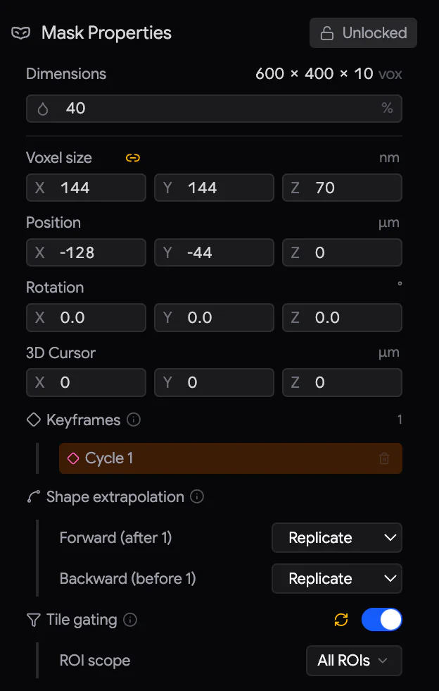
What the panel shows depends on the item:
| Drawn mask | Reference volume | Flat 2D reference |
|---|---|---|
| Dimensions, Opacity | Dimensions, On disk, In memory (with Export), Bin ×, Opacity | Opacity |
| Voxel size, Position, Rotation, 3D Cursor | Voxel size, Position, Rotation, 3D Cursor | Position (X, Y), Scale |
| Keyframes, Shape extrapolation | Register | — |
| Tile gating (with ROI scope) | Tile gating (with ROI scope, Threshold, Min pixel count, Invert threshold, Hide below threshold) | — |
Number fields work the same everywhere:
- Drag the field's icon or axis letter (X, Y, Z) sideways to change the value. Hold Shift for steps ten times finer.
- Click the number to type a value. Press Enter or click elsewhere to apply it. Esc cancels.
- Click the unit chip at the right of a row (for example µm / mm) to change the unit.
- Hover over a row's label to show Reset. Click it, then confirm with ✓. For a reference volume, Reset restores the value it had when imported. For a drawn mask, it restores the placement the mask was drawn at.
- next to Voxel size (and Scale) keeps the proportions. Scaling one axis then scales them all. Click it to scale each axis separately.
- Opacity and Bin × apply when you release the mouse. Voxel size, Position, Rotation, 3D Cursor and Scale follow your drag live.
| Row | Meaning |
|---|---|
| Voxel size | The size of one voxel. It sets the overall scale of the item compared with your tiles. |
| Position | Where the item sits: X and Y in stage coordinates, and Z in depth. |
| Rotation | Rotation in degrees around the 3D cursor. It is applied in the order X, Y, Z. |
| 3D Cursor | The point that Rotate and Scale turn around (Section 21.5). |
| Bin × | For volumes: how coarsely the volume is drawn while you drag it. A higher value is faster but blockier. Full resolution returns when you release. It does not reduce memory. |
| Export | For volumes: save the volume as a multi-page TIFF, for checking. |
21.5 Move, rotate and scale
You place masks and reference volumes with the keyboard, as in 3D software, or by dragging. The item must be selected, visible and unlocked.
| Key | Action |
|---|---|
| G | Move — the item follows the mouse. |
| R | Rotate around the 3D cursor. |
| S | Scale around the 3D cursor. Move the mouse right to enlarge. |
| X Y Z | Limit the change to one axis. For Move and Rotate, press once for the viewport's axis, and twice for the item's own rotated axis. Press a third time to remove the limit. For Scale, press once for the item's axis, and twice for uniform scaling again. |
| Numbers, ., - | Type an exact amount: µm for Move, degrees for Rotate, a factor for Scale. |
| Shift | Ten times finer while held. |
| Enter or left-click | Confirm. |
| Esc or right-click | Cancel. The item returns to where it was. |
While a transform (a move, rotation or scaling) runs, the mouse pointer is hidden. Coloured guide lines show a restricted axis: X red, Y green, Z blue. The fields in Mask Properties follow along. If Samurai loses focus (another window becomes active), the transform is cancelled.
The 3D cursor is the orange target that Rotate and Scale turn around. To place it, hold Shift and drag with the right mouse button. To keep it on one line, press X or Y during the drag. Place it on a feature you care about, so that rotation and scaling happen around that feature. Placing the cursor never moves the item.
With the mouse. With the Select tool, click an item to select it. Then drag it to move it in X and Y. A selected 2D reference has two corner handles. Drag one to resize the image, while the opposite corner stays fixed. The Hand tool only pans the view.
The strip under the viewport reminds you of the keys while a mask is selected: G move · R rotate · S scale · Shift + right-drag cursor · X/Y/Z axis · Enter confirm · Esc cancel.
Right-click a mask for Highlight in Outliner, Drive SEM Stage Here, Drive PCN here, Zoom 1:1 and Selection Scope.
21.6 Align a reference volume
Register lines up a reference volume with your acquired images. It uses pairs of matching points. For each pair, you click the same feature once in the SEM image and once in the volume.
- Select the reference volume. Display a cycle where you can recognise features in both.
- In the Register section, click +.
- Click the feature in the acquired image. The prompt next to the pointer then reads Now click the matching point on the overlay.
- Click the same feature in the volume. The pair appears as P1. Samurai is now ready for the next pair. Repeat for more pairs.
- To stop picking, click ✗ or press Esc. To apply the alignment, click ✓.
With one pair, the volume only moves. With two or more, Samurai also works out its rotation and scale, as a best fit through all pairs. From two pairs on, Deformations sets how the scale may change:
- Uniform scale: the safest choice, and the default.
- XY/Z aspect: one scale in the plane, another in depth.
- XYZ aspect: each axis separately. Use it only with many well-spread pairs.
Spread the pairs over the volume, and at different depths if you can.
While you pick points, the rest of Samurai does not respond to the mouse. You can still zoom and pan. The pointer is a crosshair everywhere.
After ✓, the section reads Aligned · RMS with the fit error. The pairs are kept as a record, and you can no longer edit them. ↺ Reset forgets the pairs so you can register again. The volume stays where the alignment put it. To undo the alignment itself, use the Reset icons on the Position, Rotation and Voxel size rows.
21.7 Tile gating
Tile gating turns a mask into a list of tiles to skip. The rule is this: a mask marks where to image. At every cycle, Samurai checks each tile in the mask's ROIs against the mask's shape at that cycle's depth:
- If the mask covers the tile, the tile is imaged.
- If the mask does not cover the tile, the tile is skipped.
For a reference volume, "covered" means that the tile contains pixels that are bright enough:
| Setting | Default | What it does |
|---|---|---|
| Threshold | 128 | A pixel counts as data when it is brighter than this (0–255). |
| Min pixel count | 0 | A tile is imaged when it contains more data pixels than this. At 0, a single data pixel is enough. |
| Invert threshold | off | Reverses the decision. Samurai images the tiles that the volume leaves empty. |
| Hide below threshold | off | Changes the display only. Pixels that are not data become transparent, so you see exactly what counts. |
Several masks can gate at once. A tile is then imaged only if it is covered by every gating mask whose scope includes its ROI.
Switch on and check
- Select the mask and switch on Tile gating in Mask Properties.
- Choose the ROI scope: All ROIs or particular ROIs. All ROIs is the default, and it also includes ROIs you add later. This mask never touches tiles in other ROIs.
- Look at the viewport. Tiles that would be skipped get a red dashed border. When a gating mask is visible, skipped tiles are also shaded red, and imaged tiles green. Use Time Travel to check a few cycles. The view shows the decision for the cycle on screen.
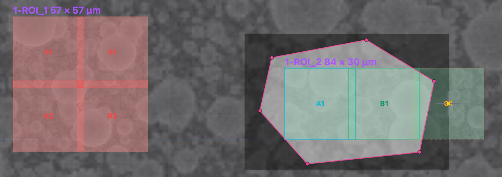
Switching on Tile gating changes nothing yet. It is only a preview. Acquisition changes only when you press Sync. The red and green shading is controlled by Tile Gating in the viewport's Overlays menu. The shading appears only when the tiles are shown.
Sync: apply the decision
Press the Sync icon next to the Tile gating switch, or the amber dot on the Masks panel header. The icon is amber when the tiles no longer match the masks. Samurai then does three things:
- It blocks the window and shows Syncing tile gating with a Z plane n / N counter. It works out the decision for every cycle, which can take minutes on long experiments. cancels the sync, and then nothing is changed.
- It sets every tile of the gated ROIs for the current cycle and every later cycle. Skipped tiles are disabled, and covered tiles are enabled. Earlier cycles are never changed.
- It locks the masks that took part, so their decision cannot change by accident.
A skipped tile is a disabled tile. It is the same as clicking Disable tile in the ROI panel. Runs and Capture ROI skip it. Sync sets every tile inside the gated ROIs. So it overrides tiles that you enabled or disabled by hand there. Tiles in other ROIs are never touched.
The Sync icon turns amber again whenever the decision may have changed. This happens after you:
- move, rotate or scale a gating mask;
- edit its shapes;
- change its threshold settings or ROI scope (a new ROI under All ROIs counts too);
- switch any mask's gating on or off;
- delete a gating mask;
- add cycles.
Showing, hiding, locking and opacity do not count. Nothing is applied automatically. Press Sync when you are ready.
To edit a synced mask, first unlock it with its padlock or with the Locked chip in Mask Properties. Make the change, then Sync again.
Release gating
To image all the tiles again:
- Unlock the mask and switch its Tile gating off. The Sync icon now offers to release the tiles. It also says how many are still disabled.
- Press Sync. Every disabled tile in the ROIs of the last sync is enabled again, from the current cycle onward. This means all of them, including tiles you disabled by hand.
Deleting a mask that gates tiles does the same release as part of the deletion. Other gating masks then need a new Sync. Deleting a mask that never gated anything leaves the tiles alone.
21.8 Lock, hide and scope
Lock a mask with the padlock in its row, or with the Unlocked / Locked chip in Mask Properties. You cannot move, reshape, re-register or delete a locked mask, or change its settings. Its Mask Properties are greyed out. Showing and hiding still work. Every Sync locks the masks that took part. Unlock a mask to edit it.
Hide a mask with to see the images underneath. You cannot select a hidden mask in the viewport, or move, rotate or scale it. But it keeps gating.
Selection Scope (') limits clicks in the viewport to one item. Scope to a mask to work on it without touching ROIs. Or scope to an ROI to reach the tiles under a mask (Section 8.5).
Undo. You can undo mask edits with Ctrl/⌘+Z. This covers shapes, keyframes, moves, settings and alignment. You cannot undo a Sync, creating or importing an item, or deleting one. Undo does not change a locked mask, so unlock it first.
EDS maps with Oxford AZtec
With an Oxford Instruments EDS detector and AZtec (Oxford's EDS software), Samurai can take element maps of chosen tiles. An element map shows where each chemical element is. Samurai takes a map when you ask, or automatically every few cycles during a run. The composition is then recorded next to the electron images as the block is cut.
22.1 Before you start
- A service engineer must switch on the EDS (Oxford AZtec) module in Settings › Service › Enabled Modules. The EDS (AZtec) panel then appears in the Imaging tab.
- The Samurai computer needs Oxford Instruments' NanoAnalysis Plugin SDK. This software kit lets Samurai talk to AZtec. Without it, connecting fails with OINA SDK not found… Install Oxford Instruments NanoAnalysis Plugin SDK on this machine.
- AZtec must be running, with a project open. Set the map settings you want in AZtec (energy range, dwell, resolution…). Samurai only starts and stops acquisitions. The settings and the data belong to AZtec.
Samurai never takes control of AZtec. You can still use the AZtec window while Samurai is connected.
22.2 Connect
The EDS (AZtec) panel has:
- Acquire EDS map at the current position.
- Edit EDS schedule.
- AZtec endpoint, the address of AZtec (only while disconnected).
- The connection badge.
- A card for each schedule. It shows the tile and how often it is mapped, with preview, enable/disable and delete.
- While disconnected, click . Enter AZtec's IP address and Port. The defaults,
127.0.0.1and22201, are for AZtec on the same computer. Click Save. - Click the red Disconnected badge. It shows Connecting... in yellow, then Connected in green. If the connection fails, a message gives the reason.
To disconnect, click the green badge and confirm. Samurai does not connect to AZtec by itself when it starts.
22.3 Take a map by hand
- Move the SEM stage to the place you want to map. You may also select the tile in the viewport. AZtec then labels the map with the tile's name.
- Click in the panel header.
Samurai takes the map where the stage is. It does not move the stage. If Imaging Addition is on, Samurai first raises the stage to the imaging position. It lowers the stage again when AZtec reports that the map is finished. While the map runs, the button turns into a spinner with Cancel EDS acquisition.
In AZtec, the map is named after the selected tile, for example 12-ROI_1-A1. If no tile is selected, AZtec numbers the map. AZtec may add a number to keep names unique.
22.4 Schedule maps during a run
A schedule asks for a map of one tile every N cycles.
- With an experiment open, click Edit EDS schedule.
- Click + (Add schedule). The new row copies the tile and interval of the row before it. The first row starts with the first tile of the first ROI, every 10 cycles.
- Choose the ROI and Tile, and set Every N cycles. To pause a schedule without deleting it, untick Enabled. Last run shows the cycle of the last map.
- Click Close. Samurai saves your changes at once.
Each schedule also appears as a card in the panel:
- enables or disables it.
- deletes it at once, without asking you first.
- Acquire EDS preview moves the stage to that tile, sets its field of view and takes a map straight away. In AZtec, the map is named
preview_<tile>_<n>.
You can use the cards during a run. Changes apply from the next tile.
During a run, Samurai checks its schedules after each tile is imaged. This happens after the debris check and the brightness correction. A map is due if the tile has never been mapped. It is also due if at least N cycles have passed since its last map. When a map is due:
- The tile shows EDS status in the viewport as a blue pulse. Its card pulses too.
- Samurai starts the map in AZtec with the site name
<tile>_c<cycle>, for example12-ROI_1-A1_c12. - The run continues when AZtec reports that the map is finished. If this takes more than 120 seconds, Samurai stops the map and moves on.
The stage is already at the tile and at the imaging height, so nothing else moves.
If AZtec is not connected when a map is due, Samurai stops and asks what to do:
- Connect now: connect and continue.
- Skip this one.
- Abort cycle: stop the run.
If you do not answer, Samurai skips the map after five minutes.
The EDS buttons are unavailable while Samurai is busy with the SEM or the stage. This covers grabbing a preview, capturing tiles, running a cycle, sweeping the knife, a quick approach and moving the stage. Hover over a button to see why.
22.5 Where the data goes
The maps belong to AZtec and are stored in its project. Samurai keeps only the schedules, in the experiment, and the site names. The site names link each map to its tile and cycle.
Scripting
Scripting lets Samurai do extra work at fixed moments of each cycle. It can click a button in the microscope's own software, run a Python program, send a command to another instrument, or wait for a signal. A script sequence is a list of actions, plus a trigger that says when the list runs.
Typical uses:
- Switch a detector or save an image in microscope software that Samurai cannot control directly.
- Start an external camera or data logger (a device that records measurements) before or after each cut.
- Run a check (a Python script) and stop the run if it fails.
- Pause the knife at a given position while another device does its job.
23.1 The Scripting panel
The Scripting panel is in the right-hand column of the Imaging tab. Sequences belong to the instrument, not to an experiment, so every experiment sees the same list. When you create or open an experiment, Samurai switches off every enabled sequence. This stops automation set up for one experiment from running in the next one. Before you start, switch on the sequences you need.
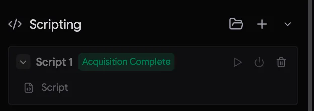 1234
1234- Load script from file, + Add script sequence, and Duplicate from existing script.
- A sequence, with its name and its trigger badge: Before Cut, After Cut, Knife Threshold, Tile Arrival, ROI Arrival, Acquisition Complete or Manual.
- Execute now, enable or disable, delete.
- The expanded list of actions.
- To edit a sequence, click it. To list its actions, click its chevron.
- A disabled sequence is dimmed and never runs.
- deletes at once, without asking you first.
- While a sequence runs, its card has a pulsing green border, and the running action pulses. A failed sequence flashes red, and a message gives the reason.
- During a run, the header buttons are unavailable. The buttons on the cards still work.
When you save a sequence, Samurai also writes it as a .json file in the scripts folder. On Windows, this folder is %LOCALAPPDATA%\Samurai3\scripts. Load script from file reads such a file back, for example on another instrument.
23.2 Create a sequence
Click +. The editor opens:
| Field | Meaning |
|---|---|
| Name | A name for the sequence. |
| Trigger Event | When the sequence runs (Section 23.3). |
| Trigger options | Shown for some triggers only: the knife position and direction, the ROI or tile, or what counts as complete. |
| Run every N cycles | Run only on cycles whose number is a multiple of N. 1 means every cycle. |
| Runs | During acquisition: only during runs. Outside acquisition: only outside runs. Always: at any time. |
| Block knife movement | Hold the knife, and block dragging it, until the sequence has finished successfully. While the sequence runs, a Script Running overlay blocks the window. |
| Actions | The steps, in order (Section 23.4). + adds a step. Each step has a Delay (s), which is a pause after it. |
Click Save.
Duplicate from existing script is the chevron next to +. It copies a sequence as Duplicate of …. The copy is disabled and ready for you to adapt.
23.3 Triggers
| Trigger | When it runs | During a run |
|---|---|---|
| Before Cut | After a cycle's imaging, before the cut. Also before an approach, a knife sweep and a manual Cut. | The run waits for it. |
| After Cut | After the cut. Also after an approach, a sweep and a manual Retract. On the first cycle of an experiment, it also runs once before any imaging. This lets you record the starting surface. | The run waits for it. |
| Knife Threshold | When the knife crosses the Threshold position (0–5256, default 2500) in the chosen Direction. The direction is Cutting, Retracting or Both. It runs at most once every 2 seconds. It reacts to the cuts of a run. It does not react to Samurai's own manual knife commands, approaches or sweeps. | Runs at the same time as the cycle. With Block knife movement, the knife stops at the crossing until the sequence ends. |
| Tile Arrival | When the stage arrives at a tile, before its image is taken. You can limit it to one ROI and tile. | The run waits for it. |
| ROI Arrival | At the first tile of each ROI, or of the ROI you name. | The run waits for it. |
| Acquisition Complete | Set by Run after. Each tile acquired: after every tile. Selected ROI finishes: when all tiles of that ROI are done. All ROIs finish: once per cycle. | The run waits for it. |
| Manual | Only when you click Execute now. | — |
Outside a run (for example, before and after an approach), a sequence runs only if its Runs is Outside acquisition or Always. During a run, sequences set to Outside acquisition are skipped. Sequences with the same trigger run in the order you created them.
23.4 Actions
| Action | What it does | Settings |
|---|---|---|
| Autoclicker | Clicks a button in another program. | Record Click: move the mouse over the button and press Ctrl+Shift+C. Esc cancels. Samurai remembers the window and a small picture of the spot. When the action runs, Samurai brings the window to the front, finds the picture and clicks it. |
| Wait | Pauses. | The Delay (s). |
| Script | Runs a Python program and reads what it prints. | The file, Args, Timeout (30 s), Expected return, and what to do on a timeout or a wrong reply. Args are extra values passed to the program. |
| Serial | Sends a command to a serial (COM) port and reads the reply. | COM Port, Baud (9600), Command, Timeout (5 s), Expected return, Match (Contains or Exact), and what to do on a timeout or mismatch. Baud is the link speed. |
| TCP Socket | The same, over the network. | Host, Port, and the same settings as Serial. |
| Wait for Pixel Change | Waits until one point on the screen changes colour, for example a status light in another program. | Pick the point. Timeout (300 s). After a timeout, the sequence carries on. |
Expected return and failures. For Script, Serial and TCP actions, Expected return is the reply you expect. Leave it empty for no check. Write any to accept any reply, as long as there is one. To look for a given text, type that text. If the reply is wrong or does not come in time, On timeout/mismatch decides what happens:
- Stop: the sequence fails.
- Continue: Samurai notes the failure and goes on.
- Retry: Samurai tries again, up to the number of times you set.
Test. Script, Serial and TCP actions have a Test button. It runs the action now and shows a Test Log. The log shows the reply, and whether a run would continue or stop.
Scripts must be Python files (.py). A script runs in the folder that holds it, and what it prints is the reply. The output goes to Samurai's log, not to the Console panel.
23.5 When a sequence fails
- If an action in a Before Cut or After Cut sequence fails with Stop, the run pauses. A failed Before Cut sequence stops the run before the knife cuts. Fix the cause, then resume the run.
- With Continue, Samurai records the failure and shows a message. The run goes on.
- For the other triggers, a failure ends that sequence early. The run continues.
Working with AI agents
An AI agent can watch Samurai and, within limits you set, operate it. An AI agent is a coding assistant such as Claude Code, Cursor or Codex. It can run on this computer or on another one. Samurai offers the agent a set of tools through MCP (the Model Context Protocol, a standard way for AI agents to use tools). A typical use is a watcher. It checks a long run every few minutes and looks at the latest images. If something goes wrong, it stops the run or tells you.
No AI model runs inside Samurai. The agent is a separate program that you install and pay for yourself. Samurai only answers its requests.
24.1 Connect an agent
The Connect an AI agent button is in the footer, on every tab.
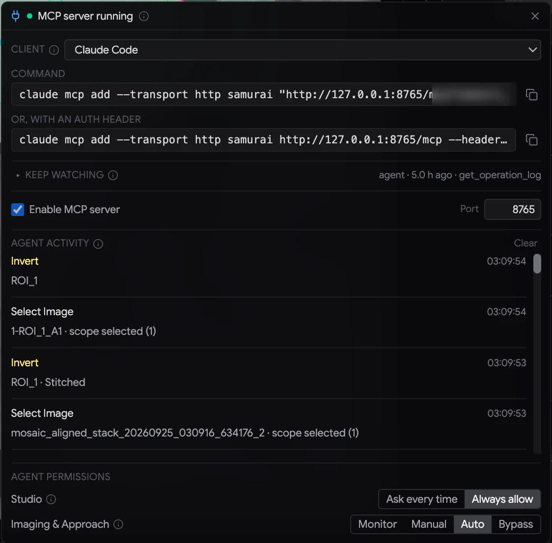
- Click Connect an AI agent.
- Tick Enable MCP server. The Port is 8765 unless you change it. The chip in the footer now reads MCP with a green dot.
- Choose your program in Client. The panel shows the exact lines to set it up. For Claude Code, for example, it shows a
claude mcp add …command. Click the copy button next to a line, and paste it where the panel says. - Start your agent and ask it to connect to Samurai.
The server accepts connections only from this computer. Each time Samurai starts, it makes a new pairing token. This is a secret code inside the address you copy. After a restart, copy the new line into your agent again. An agent on another computer connects through an SSH tunnel (a secure link between two computers). Keep watching gives the command.
Agent activity lists what agents did, newest first. The console also records every agent request and every decision.
24.2 Permissions
Agent permissions in the panel decide what an agent may do. There are two rows.
Imaging & Approach: one mode covers both tabs.
| Mode | What the agent may do |
|---|---|
| Monitor | Only read: run status, events, screenshots and images, logs, and the database (read-only). It can post observations to the console. Every action is refused. |
| Manual | Samurai first describes every change or hardware action to you. It waits for Allow once or Deny. Stopping and skipping run at once, because the safe direction never waits. |
| Auto | Changes that can be undone (tiles, ROIs) and stops run without asking. Starting and resuming imaging also run without asking, and the normal readiness checks still apply. Find Zero and Move Stage run without asking only if the knife is connected and still at 5256. Otherwise they ask. Starting an approach and making a cut still ask. Retracting the knife runs without asking. |
| Bypass | Everything runs without asking, hardware included. This lasts for this session only. It needs a second click (Arm) and turns the chip red. A restart returns to Auto. |
Studio: Ask every time (the default) or Always allow. With Ask every time, every change to a Studio project asks you first. Reading a project never asks.
Some things are never available to an agent, in any mode. They are firmware updates, knife protection, dummy and service modes, and forced clears. They also include deleting experiments, raw serial and scripting, stage limits, the cutting window, and clicking in the user interface.
The approval prompt
When an agent asks for something that needs your approval, a dialog appears on any tab. Its title is Agent requests an Imaging hardware action (or …change). It shows which tool the agent used, what it wants to do and why. Hardware actions are shown in amber.
- Allow once runs that one request.
- Deny refuses it. The same request is then refused for the rest of the session. Closing the dialog also denies it.
- If you do not answer within 120 seconds, the request is not run.
For Studio, the dialog also offers Always allow. This switches the Studio row to Always allow.
24.3 What an agent can do
| Area | Examples |
|---|---|
| Watching a run | Read the run status and which step of the workflow the operator has reached. Wait for new events. Read the console, the operation log and the database. See the viewport, an ROI or a single tile from the image store, and a tile's history over cycles. |
| Acting on a run | Stop the acquisition, skip autofocus, enable or disable tiles and ROIs, start or resume imaging, recover the imaging stage. |
| Setting up | Create an experiment or an ROI, and generate cycles. |
| Approach | Read the approach status and the optical camera. Choose a watch region (a part of the camera image) and compare it cycle by cycle. Start, adjust or stop an approach. Find zero, move the stage, cut at a fixed height and retract the knife. |
| PCN | Read the needle status. |
| Studio | Open and import data, apply operations, register (align) images, measure and export. See Section 32.2. |
| Memory | Keep notes for each experiment (remember, recall, forget). Each check can then pick up where the last one stopped. |
Some steps are meant to stay yours: connecting equipment, creating the experiment you will really run, drawing ROIs and generating cycles. If an agent notices something in these steps, it reports it to the console instead.
24.4 Keep an agent watching a run
A chat window does not keep an agent working for days. To watch a long run reliably, use a scheduled check. Every few minutes, your computer's scheduler starts the agent for one short pass. Each pass reads Samurai's monitoring brief, which tells the agent what to check. It catches up on events and images, writes its notes and reports anything worrying. Then it exits.
Open Keep watching in the panel. It has ready-made lines for your client:
- One pass, headless: a single check, run without a chat window.
- Every 5 min (scheduler): a line for Windows Task Scheduler, or for cron on macOS and Linux.
- From another machine (SSH tunnel first): for an agent on another computer.
During a run, the chip shows whether an agent is still watching:
- After 3 minutes with no call from the agent, it shows agent quiet N min in amber.
- After 10 minutes, it shows agent silent N min in red, with the message The AI agent has stopped watching the run.
Samurai cannot restart an agent itself. Check the agent's scheduler.
Samurai Studio
Samurai Studio is where you work with your images, while or after they are acquired. You can align them and stitch tiles together into one image. You can clean and enhance them, and segment structures (mark out parts such as cells). You can also measure them, look at them in 3D and export them. Studio runs inside Samurai, in its own tab. It never changes the acquired data. Everything you do is kept in a Studio project.
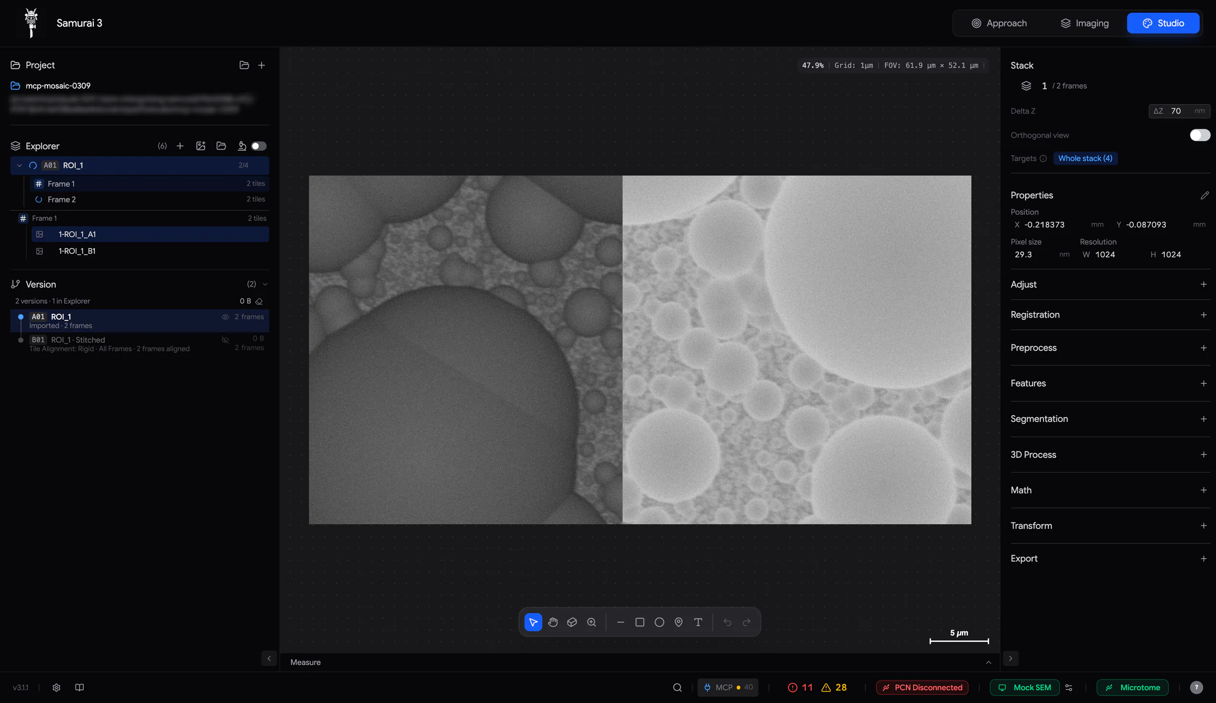
25.1 Switch Studio on
Studio is an optional module. To switch it on:
- Click the gear in the footer. Open Service and switch on Service Mode. You need a password for this.
- Open Enabled Modules and switch on Studio.
A Studio button () appears in the tab switcher at the top of the window. If you turn the module off while Studio is open, Samurai takes you back to the Approach tab.
25.2 The workspace
| Area | What it holds |
|---|---|
| Project (top left) | The open project, and buttons to open or create one (Section 25.3). |
| Explorer (left) | The stacks, frames and images of the project, and the buttons that bring data in (Section 26.4). |
| Version (bottom left) | Every version of your data, as a tree (Chapter 28, Processing and versions). |
| Viewport (centre) | The image, with a floating toolbar at the bottom (Section 27.1). Below the viewport is the Measure results panel. |
| Workbench (right) | The Stack block at the top. Below it are the tool sections: Properties, Adjust, Registration, Preprocess, Features, Segmentation, 3D Process, Math, Channels (multi-channel images only), Transform and Export. |
- To resize a sidebar, drag its border (240–420 px). To collapse it, click the chevron in its bottom corner. On a narrow window, the sidebars collapse by themselves.
- With nothing selected, the Workbench says Select an image to see details. To see an image's tools, select the image in the Explorer or the viewport.
- In 3D mode, the left sidebar is hidden and the Workbench shows the controls of the 3D view (Chapter 31, 3D views and export).
Status pill. A rounded label at the top of the viewport tells you what Studio is doing:
| Pill | Meaning |
|---|---|
| Editing Gaussian Blur. Tick or cancel to continue. | An operation is open for editing (Section 28.1). |
| Applying Gaussian Blur… | Studio is applying an operation. |
| Finish or cancel Gaussian Blur first. (amber) | You tried something that has to wait. First apply or cancel the open operation. |
Footer. Long jobs show their progress on the left of the footer, for example Importing — packaging… 3/12. Search (Ctrl+K) opens Spotlight, which finds anything in Studio as you type (Chapter 32, Spotlight and agents in Studio).
25.3 Projects
A Studio project is a folder. It holds a database file, project.sqlite, and the images Studio has written. You cannot import anything until a project is open.
Create a project
- In the Project panel, click + (New Studio project).
- Type a Project Name. Click (Select project folder) and choose where to create the project. Studio creates it as a sub-folder with the project's name.
- Click ✓ (Create project).
If the folder already contains a project, Studio refuses it. Open that project instead.
Open a project. Click (Load Studio project). Choose the project folder or its project.sqlite. The panel then shows the project's name and path.
Reopening. When Samurai starts again, Studio reopens the project you had open. It shows Reopened Studio project "…".
Saving. There is no Save button. Studio saves the project about a second after every change. If saving fails, the Project panel shows Save failed with Retry. After two failed saves in a row, Studio does not start new work until the project can be saved again.
Recovery. When a project opens, Studio tidies up after any crash. It finishes operations that were interrupted while being applied. It keeps results that were complete on disk, and removes half-written leftovers. If the database is damaged, Studio rebuilds it automatically. The damaged file is kept beside it as project.sqlite.corrupt-….
What is in a project folder
| Path | Contents |
|---|---|
project.sqlite |
The project database: stacks, frames, versions, annotations, settings. |
assets/stacks/ |
A copy of every imported file or folder, converted to OME-Zarr (an open format for large images). |
.samurai-data/stages/ |
The images of each processed version. |
.samurai-data/segmentation/ |
The labels you painted to teach the pixel classifier. |
.samurai-data/cache/, views.zarr, studio-tiles |
Copies kept to speed up the display. Studio rebuilds them when needed. |
snapshots/orthoview/ |
Snapshots of the orthogonal view (cross-sections through the stack). |
exports/ |
Rendered videos (Section 31.3). |
A streamed experiment is not copied. Studio reads it where it is, in the experiment's acquisition.zarr, and never writes there (Section 26.1).
25.4 Scrub fields and undo
In Studio, you edit numbers in scrub fields, the same way as in the Imaging tab:
- Drag the field's icon or label left or right to change the value. Hold Shift for steps ten times finer. A field without an icon cannot be dragged. You can only type into it.
- Click the value to type a new one. Enter or clicking away applies it. Esc cancels.
Undo and redo. Ctrl/⌘+Z undoes. Ctrl/⌘+Shift+Z or Ctrl/⌘+Y redoes. The buttons at the right end of the viewport toolbar do the same. Studio keeps up to 50 steps. Changes made within a third of a second count as one step. Undo covers the document: positions, names, frame order, visibility and annotations.
Processing is not undone this way. Every operation makes a new version. To go back, you check out the earlier version, which makes it the active one. Once there is nothing else to undo, Ctrl/⌘+Z does exactly that (Section 28.3). Undo is unavailable while an operation is open or running, and while images are loading.
Bringing data into Studio
Studio works on stacks. A stack is an ordered list of frames, and each frame holds one or more images. A stack can come from a Samurai experiment, streamed live while it is acquired. It can also come from image files.
| Word | Meaning |
|---|---|
| Stack | An ordered series of frames, usually one per section (cycle). |
| Frame | One position in the stack. It holds one image, or several: the tiles of a mosaic, or the ROIs of an experiment. |
| Image | One picture, with its pixel size, placed at its position in stage coordinates (mm). |
| Version | Every stack is a version, with a code such as A01. Processing makes new versions (Chapter 28, Processing and versions). |
26.1 Stream an experiment
To bring Samurai's own data into Studio, stream the experiment into a project. The whole experiment becomes one stack, with one frame per cycle (Cycle 1, Cycle 2…). Each frame holds one image per ROI (ROI_1 · Cycle 1…), each at its own stage position. Nothing is copied. Studio reads the experiment's image store (the files that hold its images) where it is. It never writes to it.
- Open or create a Studio project for the experiment.
- Open the experiment in the Imaging tab.
- In Studio, switch on Stream experiment to project in the Explorer header. The icon turns blue.
You can also click Import folder and choose the experiment folder. Studio recognises it and starts streaming straight away. If you choose a folder inside an experiment, the import dialog says This folder is part of a Samurai acquisition. It then offers Stream full experiment.
While the run continues, new cycles appear as new frames. Studio checks for them every few seconds. An ROI added during the run fills in its cycles. Images that are still being written refresh when they are complete. Frames load when you first look at them. Until then, their icon is a grey dot.
- Pause the stream by switching it off. Switch it on again to catch up. Nothing is lost or duplicated.
- If you delete a cycle frame in the project, it never comes back, even if more ROIs arrive for it.
- On the first stream into an empty project, Studio sets Delta Z (the spacing between sections) from the experiment's section thickness.
- If the experiment folder moves or disappears, the Explorer shows Stream unavailable… and keeps trying to reach it. Frames that are not loaded yet cannot load until the folder is back.
26.2 Import image files
The import buttons are in the Explorer header. You can use them once a project is open.
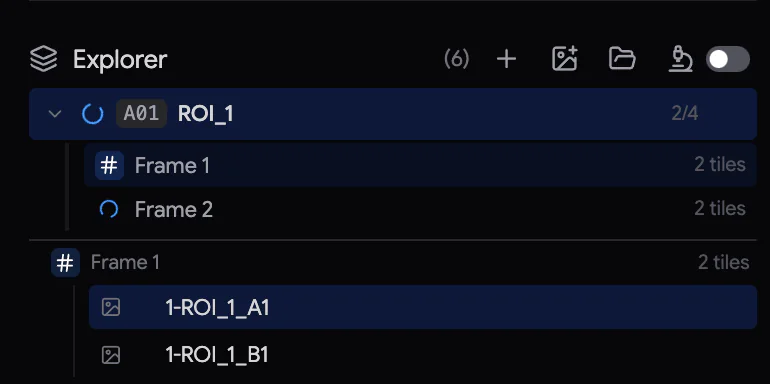 1234567
- + New frame: adds an empty frame.
- Import image file(s).
- Import folder.
- Stream experiment to project.
- A stack: its version code, name and number of frames.
- The frames of the expanded stack.
- The contents of the current frame.
One file. Click and choose a TIFF, PNG, JPEG, WebP or BMP file. You can also drag files onto the Studio tab (Drop images to import). If you drop files with no project open, Studio first asks you to create one.
- A multi-page TIFF becomes its own stack, named after the file, with one frame per page.
- A single image is added to the current frame of the active stack. If the frame already has an image, the new one is added on top as an overlay. If there is no active stack, the image becomes its own item.
Several files or a folder. If you choose several files, a selection dialog opens. The same happens with Import folder, which also searches sub-folders.
| Control | What it does |
|---|---|
| Filter by name | Keep only files whose name contains the text. |
| # (Numeric sort) | Sort img_2 before img_10. On by default. |
| Start, Count, Step | Take a range of files: start at file Start, take Count files, and use every Step-th one. |
| Import as mosaic tiles | Keep every file as its own image, grouped into frames by sub-folder. You can then stitch them (Section 29.1). |
The list shows what will be imported. Import makes one stack, named after the folder, in the order shown. Each page of a multi-page file becomes its own entry.
With Import as mosaic tiles, Load tile positions… reads the tile positions from a file. This can be a text file (path, x, y and optionally z), a Fiji TileConfiguration.txt or a TrakEM2 project. Also set the Pixel size, and whether the coordinates are the Top-left corner or the Tile center. If the layout comes out mirrored, use Swap X/Y, Invert X or Invert Y.
What is copied. Studio converts imported files into the project (assets/stacks). The project then keeps working if the originals move. Leave free disk space of about the size of the data. Files exported by Samurai bring back their metadata, the information saved with each image. This includes position, pixel size, display settings, annotations, frame names and classifier classes. Files without metadata get a pixel size of 10 nm and position 0, 0. They are marked uncalibrated.
26.3 Calibrate position and pixel size
Distances, the scale bar and 3D views need the right pixel size. While an image is uncalibrated, the pixel size label in Properties turns amber.
- Select the image. In the Properties section, click Edit properties.
- Click the Pixel size value and type the size. The unit can be nm, µm or mm. Click the unit to change it.
- Adjust Position X and Y. You can type the values, drag the X / Y labels, or drag the image in the viewport.
- Click ✓ Apply changes. ✕ discards the changes.
The pixel size applies to every image of the stack. For a streamed stack, that means every ROI. The position applies only to the selected image. These edits do not create a new version. Instead, the version's row in the Version panel shows · calibrated. Changing the pixel size changes the physical scale, not the number of pixels. To resample (change the number of pixels), use Adjust › Resize. With several images selected, Properties shows their values, but you cannot edit them there. Where the values differ, it shows Mixed.
The Crop tool is also in edit mode (Section 27.4). Apply a crop as a separate step, before or after calibrating.
26.4 The Explorer
The Explorer lists the stacks of the project. More exactly, it lists the versions you are looking at:
- The version that is checked out (the active one).
- Any versions you have selected.
- Any versions you keep shown with the eye in the Version panel (Chapter 28, Processing and versions).
To show the frames of a stack, click its chevron.
Frame status icons
| Icon | Meaning |
|---|---|
| # | Ready. |
| Grey dot | Not loaded yet. Streamed frames load when you view them. |
| Spinner | Working. Blue: loading. Sky blue: importing. Amber: being processed. Violet: classifying. |
| Red ✕ | Failed. The tooltip gives the reason. Click to try again. |
| — | Empty frame. |
A frame row also shows a summary, such as 2 ROIs, 3 tiles or 1 image + 1 overlay. A green pencil means the frame has painted classifier labels. Below the list, the contents of the current frame list its images and annotations. Hover over one to see centre, show/hide and delete.
Selecting. Click a stack header to select the whole stack and check it out. Click frames or images to select them. Ctrl/⌘-click adds or removes an item. Shift-click selects a range. Esc clears the selection. The selection is what operations work on (Targets: what the next operation changes).
Renaming. Double-click a stack or frame name, type the new name and press Enter. F2 renames the selected stack. Frame names stay with the frames when you reorder them.
Reordering and combining. Drag frames up and down within a stack. Drag an image onto another frame to move it there. Drag one stack header onto another to combine the two stacks.
Right-click menus
| On | Items |
|---|---|
| A stack | Rename, Collapse Other Stacks, Select All Frames, Clear Selection, Filter Frames..., Sort by Numeric Filename, Reverse Frames, Reload Stack Frames, Duplicate Stack, Combine Selected Stacks, Consolidate Stack, Delete Stack |
| Frames | Select All Frames, Invert Selection, Clear Selection, Reload Selected Frames, Duplicate (copies go to the end), Duplicate to New Stack, Split to New Stack, Move to Top / Up / Down / to Bottom, Reverse Selected, Delete Selected Frames |
| An image | Duplicate Image, Remove from Frame, Measure..., Delete Image |
Filter Frames... keeps only a range of frames. It uses the same Start / Count / Step controls as the import dialog. Consolidate Stack merges a stack into one image store. It is for stacks whose frames come from separate files, or whose order you changed. Some operations need this. It is not needed, and not offered, for streamed stacks and mosaics.
Explorer shortcuts
| Keys | Action |
|---|---|
| Ctrl/⌘+A / I | Select all frames / invert the selection. |
| F2 | Rename the selected stack. |
| Ctrl/⌘+F | Filter frames. |
| Ctrl/⌘+D | Duplicate the selected frames (or images). |
| Ctrl/⌘+Shift+D / X | Duplicate / split the selected frames into a new stack. |
| Ctrl/⌘+J | Combine the selected stacks. |
| Ctrl/⌘+Shift+C | Collapse the other stacks. |
| Home / End / Alt+↑ / Alt+↓ | Move the selected frame to the top / bottom / up / down. |
| Shift+R | Reverse the selected frames (or the whole stack). |
| Alt+R | Reload. |
| Shift+Del | Remove the selected images from their frames. |
| Del | Delete the selection. |
| ↑ / ↓ | Previous / next frame. |
Viewing and annotating in Studio
The Studio viewport shows one frame of a stack at a time. It uses real-world coordinates: each image sits at its stage position and is drawn at its pixel size. So the grid, the scale bar and every readout are in mm, µm or nm.
27.1 Navigate
The viewport works the same way as the Imaging viewport (Section 8.2):
| Input | Action |
|---|---|
| Scroll with the mouse wheel or two fingers | Pan. Shift + wheel pans sideways. |
| Pinch, or Ctrl/⌘ + wheel | Zoom around the pointer. Each notch zooms 15 %, or 3 % with Shift. |
| Middle-button drag, or hold Space and drag | Pan, whatever tool is active. |
| F (or numpad 0) | Fit the frame in the view. |
| Numpad 1–4 | Zoom to 100 %–400 % (one image pixel = 1–4 screen pixels). |
| Numpad . | Centre on the selected image. |
If you want a plain scroll to zoom instead, set Settings › General › Scroll Wheel to Zoom. It applies to both the Imaging and Studio tabs.
The info bar at the top right shows the zoom, the grid spacing, the field of view and the pointer's position. At 100 % zoom, one image pixel fills one screen pixel. G shows or hides the dot grid, and K the scale bar at the bottom right.
27.2 The toolbar

| Tool | Key | Use |
|---|---|---|
| Select | V | Select images and annotations. Drag across an empty area to select annotations with a box. |
| Hand | H, or hold Space | Pan. |
| Crop | C | Crop the selected image. Works only while you edit Properties (Section 27.4). |
| Volume Selection | — | Draw the region you want to open in 3D (Chapter 31, 3D views and export). |
| Loupe | hold M | A magnifier around the pointer. Click the button to keep it on. |
| Line | L | Draw a line. Its length shows while you draw. |
| Rectangle | R | Draw a rectangle. Hold Shift for a square. |
| Ellipse | O | Draw an ellipse. Hold Shift for a circle. |
| Point / landmark | P | Click to place a point. Use it as a landmark, or to mark an object you are counting (Section 30.3). |
| Brush, Erase | B, E | Paint or erase classifier labels. They appear while a classifier class is chosen (Section 30.1). [ and ] change the size. |
| Undo, Redo | Ctrl/⌘+Z, Ctrl/⌘+Shift+Z | Undo and redo (Section 25.4). |
27.3 Annotations
Lines, rectangles, ellipses and points are annotations: shapes drawn over the images, separate from the pixels. Use them to mark, to measure, or to choose where an operation applies.
- Draw a shape by dragging with the Line, Rectangle or Ellipse tool. The tool then returns to Select, with the new shape selected. Shapes snap to image edges and centres, and to other shapes. Purple guide lines show when they snap. Hold Shift for 45° lines, squares and circles.
- Select a shape by clicking it. Drag its handles to change its shape. The arrow keys move it by one image pixel. Add Ctrl/⌘ to move 10 pixels, or Shift to move 0.1 pixel. To copy, paste or duplicate it, press Ctrl/⌘ with C, V or D. Delete deletes it.
- When shapes are selected, the Workbench shows their Properties, Appearance and Fill. Properties holds the position and size. Appearance holds the colour, line width and opacity.
- A new shape belongs to the frame you drew it on. To put it on every frame, select the whole stack in the Explorer. Then right-click the shape and choose Apply to all frames. The shape is now linked across frames. Unlink (per-frame only) reverses this. If you delete a linked shape, Studio asks you to confirm, because the shape disappears from every frame.
- The Explorer lists the annotations under the current frame. There you can centre the view on each one, hide it or delete it.
Process inside a shape. If exactly one shape is selected, the Workbench shows Pixel operations. These are operations from Adjust, Preprocess, Features, Segmentation and Math. They change only the pixels inside the shape, on the current frame. Operations that change the size, type or channels of the image are not offered there.
27.4 Crop
- Select the image. In Properties, click Edit properties.
- Choose Crop (C) and click the image. Drag the handles, or drag inside the crop box. The size is shown in pixels.
- In Properties, click ✓ Apply changes. To cancel the crop, press Esc.
The crop makes a new version of the stack, with every frame cropped. The original is kept. Apply a crop on its own. Do not combine it with changes to position or pixel size.
27.5 Contrast and the loupe
Studio has no permanent brightness and contrast control. To change the display levels, open Adjust › + › Histogram:
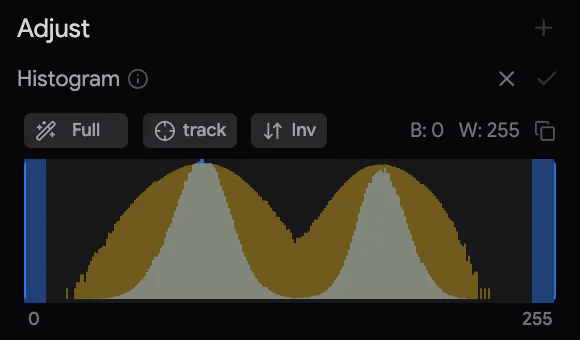
- The histogram is calculated from all the images you have selected in the Explorer. The black and white points apply to all of them together.
- Drag the black and white handles, or use the auto button. Its label shows the current level: Full, Fit, then a clip percentage (Section 16.1). The clip percentage is the share of pixels set to pure black or white. Click the button for a stronger clip. Right-click it to step back.
- track re-applies the automatic level when you select other images. Inv inverts the contrast.
- ✓ Apply histogram writes the levels into the pixels, as a new version. ✕ restores the previous display.
The loupe shows the pixels around the pointer, about four times larger. It includes labels and masks. Hold M to show it, or pin it on with .
27.6 The Stack block
The Stack block sits at the top of the Workbench. It appears for stacks of more than one frame, and for mosaic frames.
Moving through frames. The row reads n / N frames. To change frames:
- Drag its icon sideways. Hold Shift to go faster.
- Turn the mouse wheel over it: one frame per notch, or ten with Ctrl/⌘.
- Click the number and type a frame.
- In the Explorer's frame list, press ↑ or ↓.
Delta Z is the distance between frames (default 50 nm). It sets the depth scale of the orthogonal and 3D views, of reslices and of meshes. It also sets the Z spacing given to new imports. Studio sets it for you when you stream an experiment into an empty project.
Targets: what the next operation changes
Operations work on the selection in the Explorer. The Targets row in the Stack block tells you what this means for the next operation:
| Targets | When |
|---|---|
| Whole stack (N) | The stack header is selected, which selects all its frames. |
| Selection (N) | Some frames or images are selected. |
| Select images first (amber) | Nothing is selected. Apply will refuse to run. |
| Vector (1 frame) | One shape is selected. The operation works inside the shape, on the current frame. |
| … full-stack op — runs on every frame | The chosen operation changes the stack's size, type or layout. So it always processes every frame. |
27.7 The orthogonal view
Switch on Orthogonal view in the Stack block to see the stack as a volume, cut in three directions at right angles. Next to the usual XY frame, two cross-sections, XZ and YZ, cut through all frames.
- Click or drag in XY to move the cyan crosshair. The mouse wheel over XY steps through frames.
- Click or drag in XZ or YZ to move the crosshair. This also jumps to the frame you clicked.
- Set Delta Z correctly first. All panes share one scale, and depth is drawn in its true proportion (Delta Z ÷ pixel size).
- While you move, the cross-sections appear quickly at low resolution. They sharpen when you stop. Volume cache … · Clear at the top right frees the memory they use.
- Capture orthogonal view saves the three panes as one picture, in
snapshots/orthoview. It also adds the picture to the project as a new frame.
To return to the normal viewport, switch Orthogonal view off.
Processing and versions
Every processing step in Studio is non-destructive: an operation never changes the images it reads. Instead, it makes a new version of the stack. The earlier versions stay available. You can compare with them, go back to them, or start a new branch from them.
28.1 Apply an operation
- Select what to process in the Explorer. Select the stack header for every frame, or select some frames or images. The Targets row confirms your choice (Targets: what the next operation changes).
- Click + on a Workbench section, for example Preprocess. Choose a group and then a Method, or choose a method directly.
- Set the parameters. To see what a parameter does, hover over its name. A moment after each change, a preview of the current frame appears in the viewport. Nothing is written yet.
- Click ✓ (Apply operation) to process the targets. To discard, click ✕ or press Esc.
While a method is open, the status pill at the top of the viewport reads Editing … Tick or cancel to continue. Studio then locks everything else. You cannot open another method, change the selection, change frames or versions, or undo. If you try, the pill shows Finish or cancel … first. for a moment.
Some methods cannot be previewed, because they need the whole stack. They say so. A few methods work only on certain images. On other images they are greyed out and show the reason, for example integer images only or multi-channel images only.
While it applies, the pill reads Applying …. The new version appears at once in the Version panel, with a pulsing yellow dot and its progress (done/total). Studio starts with the frame on screen and works outward from it. When the operation finishes, Studio checks out the new version: the viewport and the Explorer switch to it.
28.2 Versions
Every stack in a project is a version, labelled with a code:
- The first imported stack is A01. The next import is B01, then C01, and so on.
- Processing A01 gives A02. Processing A02 gives A03. The number counts the steps from the original.
- If you process the same version a second time, you start a new branch (a separate line of versions). It gets a new letter at the same step: B03 from A02.
Codes never change. A code is never reused while any version with that letter exists. After Z come AA, AB….
The Version panel (bottom of the left sidebar) lists every version as a tree:
- Each row shows the code and the name. The name is the operation that made the version, for example Gaussian Blur.
- A detail line shows Imported · 120 frames, or the operation with its parameters, for example Gaussian Blur: Sigma 1. It adds · from frames 3, 4 when only some frames were processed. It adds · calibrated when the position or pixel size was edited.
- The dot is blue for the version you are on. It is pulsing yellow while that version is being written.
- On the right, the row shows the disk space the version uses and its number of frames.
- The panel header shows the number of versions and how many are in the Explorer. It also shows the total disk space used by processed versions.
Check out a version by clicking its row, or its stack in the Explorer. The viewport then shows it, and the next operation reads it. Double-click a row to rename the version. The panel is unavailable while a method is open or an operation runs.
Which versions the Explorer lists. To keep the Explorer short, it lists only:
- the version you have checked out
- versions you have selected
- versions you keep with the eye in the Version panel.
Checking out another version replaces the one on show, unless you kept it. In the Version panel, rows of versions that are not in the Explorer are dimmed.
Carried frames. When an operation processes only some frames, the new version still has every frame. The other frames are carried from its parent: they are shown as they were, without being copied. Only the frames that changed take disk space.
28.3 Going back
- Click an earlier version in the Version panel to go back to it. Nothing is lost: the later versions stay.
- When there is no other edit left to undo, Ctrl/⌘+Z checks out the parent version. Ctrl/⌘+Shift+Z (or Ctrl/⌘+Y) steps forward again.
- To try something different from an earlier version, check it out and apply another operation. This starts a new branch.
28.4 Delete versions and free disk space
To delete a processed version and its images from disk, right-click it in the Version panel and choose Delete Version…. Studio asks you to confirm first. If other versions were made from it, they are deleted too. In that case the menu item reads Delete Version + N derived…. You cannot delete imported versions this way. A version that is being written cannot be deleted until it finishes.
The right-click menu also offers Rename..., Keep in Explorer / Show Only While Checked Out and Collapse Other Stacks in Explorer.
Prune ( in the panel header) frees disk space that no version uses. It removes images left behind by crashes or by stacks removed from the Explorer. It also removes cached data, which Studio rebuilds when needed. To prune:
- Click . Studio checks what could be removed and shows Checking what no version reads….
- If it finds something, it asks, for example: Free 2.3 GB: 3 orphaned store(s) and 5 cached composite(s)? Click ✓ to remove them.
Prune never touches imported data, or anything a version still reads.
28.5 Streamed experiments, mosaics and consolidation
Streamed experiments. A streamed stack holds several ROIs in each frame. Operations process it one ROI at a time. The images of each ROI form their own Z stack, which is processed on its own. The results are then put back together as one new version with the same ROIs. The footer shows the ROI in progress, for example Gaussian Blur · ROI_2 (2/3). 3D operations work within each ROI.
Mosaics. A frame with several tiles is an unstitched mosaic. You can apply simple per-image operations to it, tile by tile. Anything that changes the size or needs the whole stack must wait until the tiles are stitched (Section 29.1).
Consolidation. Some stacks have frames that come from separate files, or frames that you reordered. Such a stack must be consolidated (merged into one store) before operations that depend on the order of the frames. To do this, right-click it in the Explorer and choose Consolidate Stack. Studio tells you when this is needed. Processed versions and streamed stacks never need it.
28.6 Long operations
Studio never gives up on an operation because it takes a long time. Large stacks can take hours. If an operation stops reporting progress and the computer shows it is doing no work, a message appears: … may be stuck. It says what the operation was doing, and for how long. Nothing has been cancelled. Choose Cancel to stop it. Or choose Stop waiting to carry on without it. It keeps running in the background. If it starts moving again, Studio tells you.
- If Samurai closes or crashes during an operation, the operation resumes by itself the next time you open the project. It skips the frames that are already done.
- Operations on whole volumes check that they fit in memory. Large ones are processed in slabs (groups of frames). If an operation cannot work in slabs, Studio refuses it and shows the memory needed (Volume too large for …).
- If you cancel, or the operation fails, Studio discards the unfinished version. The source is not changed.
28.7 Operation reference
Defaults are shown in brackets. "Stack" methods work on the whole stack at once. You cannot preview them on one frame, or the preview is only a rough guide.
Adjust
| Method | What it does |
|---|---|
| Histogram | Set black and white points on the selected images, and write them into the pixels (Section 27.5). |
| Contrast / Intensity › CLAHE | Boost contrast locally, region by region (clip limit 0.03, kernel size auto). |
| › CLAHE (Exact, Any Size) | The same, for very large images. It works exactly, block by block (clip limit 1.6, block 512 px). |
| › Gamma Correction | Brighten the mid-tones with a gamma below 1, or darken them with a gamma above 1 (gamma 1). |
| › Levels (shared) | One pair of black and white points for the whole stack, plus the output type. Always runs on all frames. |
| › Log Transform, Square Root Transform | Compress the bright values. |
| › Match Brightness Over Z | Stack method. Make the brightness of every frame match a reference frame (percentiles 10–90, max gain 3). |
| Resize | Set a new width and height in pixels, or a factor (1×–8×). Choose the resampling: Average (best for shrinking EM images), Bilinear, Nearest or Lanczos. The pixel size changes to match. |
| Enhance Contrast | Percentile Stretch (saturated pixels 0.2 %) or Histogram Equalization. The limits come from Each frame or from the Whole stack. |
Preprocess
| Group | Methods |
|---|---|
| EM Cleanup | Remove Horizontal Bands, Remove Vertical Curtaining (smoothing 25, strength 1). Repair Z Continuity works on the whole stack. It replaces a damaged section with a copy of the nearest good section. |
| Denoise | Non-local Means (h 0.08), Bilateral Denoise, Total Variation Denoise (weight 0.08), Despeckle (3×3 median), Remove Outliers (radius 2, threshold 50). |
| Background | Subtract Background (radius 50), Flat Field Correction (sigma 50), Black Top Hat / White Top Hat (radius 15), and Dark Reference Correction, which subtracts a dark reference image. |
| Filters | Gaussian Blur (sigma 1), Mean Filter, Median Filter, Minimum, Maximum, Local Variance, Sharpen, Smooth 3x3, Unsharp Mask (radius 2, weight 0.6). |
| Frequency | FFT Bandpass smooths detail finer than 3 px and removes shading coarser than 40 px. Destripe (Fourier Notch) removes horizontal or vertical stripes. FFT (Power Spectrum) makes an image of the power spectrum, which shows repeating patterns. |
Features
| Group | Methods |
|---|---|
| Feature Enhancement | Difference of Gaussians (sigma 1 and 3), Morphological Gradient. |
| Edges | Canny Edges, Sobel Edges, Scharr Edges, Prewitt Edges, Laplacian Edges, Laplacian of Gaussian. |
| Ridges | Frangi Ridge Filter and Sato Ridge Filter, for membranes and filaments. |
| Texture | Local Entropy, Local Variance. |
Segmentation
| Group | Methods |
|---|---|
| Pixel Classifier | Train a classifier by painting examples (Section 30.1). |
| Threshold | Otsu, Li, Yen, Triangle (automatic), Multi-Otsu Threshold (3 classes), Adaptive Threshold (block 51), Hysteresis Threshold. |
| Morphology | Dilate, Erode, Open, Close, Fill Holes, Outline, Distance Map, Watershed 2D. |
| Binary | Manual Threshold, Label Components, Remove Small Objects (100 voxels), Keep Largest, Find Maxima, Find Minima. |
3D Process
All are stack methods: Gaussian Blur 3D, Median Filter 3D, Fill Holes 3D, Remove Small Objects 3D (500 voxels), Watershed 3D.
Math
Add Constant, Subtract Constant, Multiply Constant, Divide Constant, Minimum, Maximum, Invert, Absolute Value, Exponential Transform, Reciprocal Transform, Bitwise AND / OR / XOR (integer images), Convert Type (8-bit, 16-bit or 32-bit float, always all frames), and the Image Calculator.
The Image Calculator combines two images pixel by pixel. It can Add, Subtract, Multiply, Divide, Min, Max, And, Or, Xor or Copy. The two images must be the same size. Choose the Second image and which of its versions to use. Then click Calculate. The result is saved as a new file and added to the project.
Channels
These work on multi-channel (colour) images. Extract takes out one channel as a new version. Create RGB composite stage builds a colour image from three channels.
Transform
| Method | What it does |
|---|---|
| Flip Horizontal, Flip Vertical | Mirror the images. |
| Rotate | Rotate by an angle, from −180° to 180°. Use expand to keep the corners. Always runs on all frames. |
| Z Projection | Combine a range of frames into one image, using max, min, mean, sum, median or std (standard deviation). The result is saved as a TIFF and added as a new image. |
| Reslice | Cut the stack along another axis: Top (XZ) or Left (YZ). Use all rows or a range. The result is a new stack in the project. Its vertical spacing is Delta Z. |
| Local Registration | Experimental. Corrects small local distortions between frames (Chapter 29, Registration and stitching). |
| Extract Channel, RGB Channel Composite | The same as in Channels. |
Registration and stitching
Registration lines images up with each other. Studio offers three kinds, all under Registration › + in the Workbench. There is also an experimental local correction under Transform.
| Method | Use it for |
|---|---|
| Tile Alignment | Stitching the overlapping tiles of a mosaic into one image per frame. |
| Stack Alignment | Removing the X/Y drift from one frame to the next in a stack. |
| Landmark Alignment | Fitting one image or stack onto another, using points you click on both. For example, a light-microscopy image onto an EM overview. |
| Local Registration (Transform) | Correcting small, uneven distortions between frames. Experimental. |
29.1 Tile Alignment: stitch a mosaic
Tile Alignment works out how the overlapping tiles of a frame fit together. Then it blends them into one image.
- In the Explorer, select what to stitch: the current frame, some frames, or the whole stack (all frames). For the current frame, opening the frame is enough. The Targets row shows your choice.
- Click Registration › + › Tile Alignment.
- Choose the Method. Rigid shifts the tiles and also corrects one rotation that they all share. Translation only shifts the tiles in X and Y.
- Adjust the options if needed. Then click ✓. The button reads Align and stitch current frame or Align and stitch all frames.
| Option | Default | What it does |
|---|---|---|
| Search radius | 100 px | How far a tile may be from its expected position. |
| Min overlap | 10 % | The smallest overlap between neighbouring tiles for a match to be trusted. |
| Settle rows | 0 px | Rows at the top of each tile that are left out of the blend. Use this when the first lines of a scan are distorted. |
| Global solve across frames | off | When you stitch all frames, solve every frame together. This keeps the mosaic steady from one section to the next. |
| Level tile brightness | off | Even out brightness differences between tiles. |
| Flatten section illumination | off | Remove gradual shading across the stitched image. |
For the current frame, Studio replaces its tiles with one stitched image in the same stack. For all frames, Studio stitches every frame that has at least two tiles, and skips single-image frames. It creates a new stack named … · Stitched. While it runs, a preview stack in the Explorer shows each frame as it is finished.
The tiles must overlap. Their images must be readable and share one pixel size, calibrated and square (equal in X and Y). If a frame has fewer than two tiles, the button says so.
29.2 Stack Alignment: remove drift
Stack Alignment measures the shift between frames by correlation, which finds where two frames match best. Then it moves every frame to cancel the shift.
- Select an image of a multi-frame stack.
- Click Registration › + › Stack Alignment.
- Choose the Reference and the options (see the table below).
- Click ✓ (Align all frames in the stack).
| Option | What it does |
|---|---|
| Reference: Each vs previous (default) | Align each frame to the one before it, and add up the shifts. Best for gradual drift. |
| Reference: Each vs first frame | Align every frame to the first one. Best when the structure changes little. |
| Full-frame residual pass | Measure again on the aligned frames, and correct what is left. Slower, but more precise. |
| Crop to common valid region | Crop the result to the area that every frame covers, so no empty borders remain. |
| Jitter correction only | Remove only quick jumps from frame to frame, and keep slow, real motion. Smooth sets the number of frames to smooth over (10). |
Stack Alignment always processes every frame and creates a new version. On a streamed experiment, Studio measures the shifts on the selected ROI. It then applies them to the ROIs being processed.
29.3 Landmark Alignment: fit one image onto another
- Import both images (or stacks) into the project.
- Click Registration › + › Landmark Alignment. Choose the Reference, the image that stays in place. Then choose the Moving image, the one to fit onto it.
- Choose the Model. It sets how the moving image may change:
- Affine is the default. It allows stretching and shear (slanting).
- Similarity allows rotation, scale and shift.
- Rigid allows rotation and shift only.
- Projective allows perspective.
- Click Add pair. Click a feature in the reference, then the same feature in the moving image. The viewport prompts you: 1 Pick reference in …, then 2 Pick matching point in …. Repeat until you have at least 3 pairs (4 for Projective), spread over the image.
- Click Compute to see the fit error for each pair. Click Preview to see the result.
- Click ✓ Apply. Studio warps every frame of the moving stack onto the reference, as a new version.
A pair with a large error is probably a mis-click. Remove it with its ✕ and add it again. With four or more pairs, Affine and Projective fits automatically ignore obvious outliers (pairs that clearly do not fit).
29.4 Local Registration
Transform › + › Local Registration corrects small, uneven distortions between one frame and the next. They can come from section compression, for example, or from charging (a build-up of electrons that spoils the image). It measures the shifts on a grid of small patches, then bends each frame to match. It is experimental and cannot be previewed. Its buttons read Accept local registration (apply) and Reject local registration (discard). Afterwards, compare the new version with its parent, and delete it if it is not better. It cannot run while the stack has annotations, labels or masks.
Segmentation and measurement
Segmentation divides an image into meaningful parts, such as membranes, cells, organelles and background. Studio offers an interactive Pixel Classifier that learns from examples you paint. It also offers classic methods based on a threshold (a brightness cut-off between objects and background). Measurement tools then give numbers: intensities, areas, particle counts and profiles.
30.1 The Pixel Classifier
You paint a few strokes of each class (each kind of structure you want to find). A random-forest classifier (a learning method built from many decision trees) learns from them and predicts the class of every pixel. You correct its mistakes with more strokes until the result is right. Then you generate the mask, an image that gives the class of every pixel.
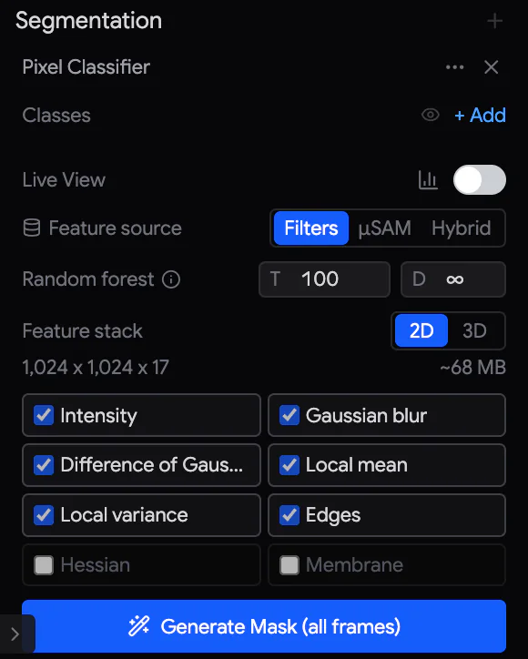
Set up
- Select the stack and click Segmentation › + › Pixel Classifier. The panel opens, and Studio switches on the label and mask overlays.
- Click + Add for each class you need, up to ten. For example: Membrane, Cytoplasm, Background. To rename a class, double-click its name. To change its colour and opacity, click its colour. To hide it, use the eye.
Paint and train
- Click a class to choose it. The toolbar then shows Brush (B) and Erase (E). Paint on the image. With the brush, Shift+drag erases. [ and ] change the size. The number keys 0–9 choose a class.
- Switch on Live View. Then, 300 ms after each stroke, the classifier retrains and shows its prediction as a coloured mask. In the Explorer, a frame with painted labels has a green pencil.
- Paint where the prediction is wrong, not where it is already right. A few strokes of each class on several frames work better than many strokes on one frame.
- Alt+L shows or hides the painted labels. Alt+M shows or hides the mask. Hold M for the loupe, a magnifier around the pointer.
Settings
| Setting | What it does |
|---|---|
| Feature source | What the classifier measures at each pixel. Filters uses standard image filters. μSAM uses a neural network, if installed. Hybrid uses both. |
| Random forest | T: the number of trees (100). D: the maximum depth of a tree (∞). |
| Feature stack | 2D looks at each frame alone. 3D also looks at neighbouring frames. With 3D, Z anisotropy takes thicker sections into account. |
| Feature families | Tick the kinds of features to use: Intensity, Gaussian blur, Difference of Gaussians, Local mean, Local variance, Edges, Hessian, Membrane. |
The chart icon next to Live View opens Diagnostics. It shows how well the classes separate, the labels you painted, and the features the classifier sees.
Generate the mask
Train with at least two classes first. To make the mask for the current frame, click Generate Mask. To make it for every frame, select the whole stack in the Explorer and click Generate Mask (all frames). The result is a new stack named … · Pixel Classifier. Its pixels are class numbers.
The ⋯ menu offers Clear Frame Labels & Masks and Clear Stack Labels & Masks. They keep generated mask stacks. Closing the panel with ✕ keeps your labels and masks.
To save the classes as a TIFF for other software, use Export › + › Export Segmentation Stack (Section 31.3).
30.2 Threshold-based segmentation
If the structures stand out by their brightness, a chain of simple operations is often enough. Apply each step from Segmentation › + (or 3D Process). Each step makes a new version, so you can go back to any step. A typical chain:
- Denoise (Preprocess), for example with Non-local Means.
- Threshold: Otsu or Li for an automatic level, or Manual Threshold (Binary) to set your own.
- Morphology, to clean up shapes: Open to remove specks, Close to bridge gaps, and Fill Holes.
- Binary: Remove Small Objects, then Label Components to give every object its own number.
- If objects touch, Distance Map and Watershed 2D (or Watershed 3D) separate them.
The methods are listed in the operation reference (Section 28.7).
30.3 Measuring
Quick statistics. Select an image and press Shift+M, or right-click it and choose Measure…. The Measure dialog shows Min, Max, Mean, Std (standard deviation) and the Area. The area is in pixels and, if the image is calibrated, also in mm². The numbers are for the version on screen, inside the crop region if there is one. Export CSV saves the numbers.
Lengths. A line shows its length while you draw it.
The Measure dock
Under the viewport, the Measure strip opens a results dock. Drag its top edge to resize it. The dock has these tabs:
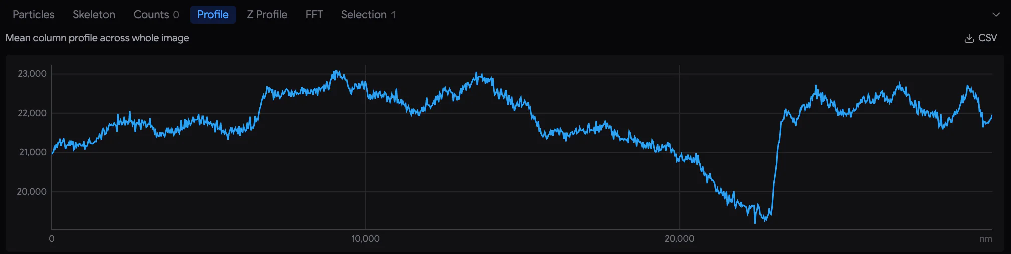
| Tab | What it gives |
|---|---|
| Particles | Finds objects above a Threshold, or from a Label map (objects already numbered). Lists their area, intensity, shape and position. Works on the Current frame, All frames (2D) or the Volume (3D), inside the selected shape or over the whole image. Click a row to jump to the object. |
| Skeleton | For filaments and networks. Reduces objects to centre lines. Gives their total length and the numbers of branches, end points and junctions. |
| Counts | Counts objects by hand. Add a counting class with + Add (up to nine), and choose it with the number keys. Then click objects with the Point tool (P). The table lists each marker. |
| Profile | The intensity along the selected line, or across a rectangle or ellipse. For a point, the intensity through all frames (a Z profile). With nothing selected, the mean of each column across the whole image. |
| Z Profile | A statistic of the selected region in every frame: Mean, Median, Std dev, Min, Max or percentiles. Use it to check brightness or quality through the stack. |
| FFT | The power spectrum of the frame or the selected region, which shows repeating patterns. It also gives the period (repeat distance) of the strongest peak. |
| Selection | Live statistics of the selected images or shapes. |
You can save every table with its CSV button. The crosshair button shows the results as markers on the image.
3D views and export
Studio can show any part of a stack as a 3D volume. It can also export images, stacks, videos, meshes (3D surfaces) and segmentations for other software.
31.1 Open a region in 3D
- Click Volume Selection in the toolbar and drag a rectangle over the region. Drag the corners of the cyan box to adjust it. Right-click the box for Fit to image.
- In the 3D Volume Selection panel, choose the Starting frame and End frame. Then set the Bin (1×–4×). Binning averages 2×2×2, 3×3×3 or 4×4×4 voxels into one, to make the volume smaller.
- Check the size under Voxels and RAM. Above 500 million voxels, tick Override to go ahead.
- Click Send to Volume Viewer.
The pixel size of the images must be set, and Delta Z (the distance between frames) must be right. Otherwise the volume looks squashed or stretched. Studio reduces a very large region to 2 GB at most. The view then says displayed at …%.
In the 3D view:
- Drag to turn the volume and scroll to zoom. Shift+drag (or drag with the middle button) moves it.
- Reset camera (top right) returns to the starting view.
- Exit 3D (top left) or Esc returns to the 2D viewport.
- The badge shows the region's size (for example 120×80 µm × 200) and the binning.
If the 3D view fails, a card offers Restart renderer or Return to 2D.
31.2 The Volume Renderer panel
In 3D mode, the Workbench becomes the Volume Renderer panel.
| Section | What it controls |
|---|---|
| Presets | Colour maps: fire, ice, viridis, red_hot, magenta_cyan, grayscale… You can save your own under a name. |
| Transfer Function | The colour for each intensity. Paint the red, green and blue curves. |
| Alpha Curve | The opacity for each intensity, drawn over the histogram. Offset raises or lowers the whole curve. To see structures inside, make the background transparent. |
| Mode & Sampling | Renderer: Basic is always available, GPU is faster, and Full Light gives realistic light and shadows but is slower. Mode: Composite is the normal view. MIP shows the brightest voxel along each line of sight, and Min IP the darkest. Additive adds them up. Iso shows a surface at one intensity. Sampling sets the step size along each line of sight. |
| Iso Threshold | The intensity of the surface in Iso mode (default 128). |
| Scene | Z aspect to stretch the depth, the background colour, and a plane under the volume. |
| Clipping | To look inside, cut the volume along X, Y, Z or the viewing direction. |
| Full Light options | Quality, light direction, shadows, ambient occlusion (soft shadows in corners), path tracing. |
Save volume view to Explorer keeps the view as a Volume view item in the Explorer, with its region, camera and settings. Double-click the item later to reopen it. Reset all controls returns the panel to its defaults.
31.3 Export
Export › + offers these exports:
| Export | What you get |
|---|---|
| Export Selected Stack | The whole stack as one multi-page TIFF, or a folder of PNG or JPEG files. The TIFF can be compressed with LZW, Deflate or Zstd. |
| Export Selected Frames | The same, but only the selected frames. |
| Export as Video | An MP4 video of all frames or a range. FPS sets the speed (default 10). CRF sets the quality (default 18; lower is better). |
| Render Video… | An MP4 video in the project's exports folder. A Fly-through plays the sections in turn, with fades and section labels. A Turntable turns the volume through 360°. |
| Export Mesh | A 3D surface of a mask stack (OBJ or STL, in µm), for 3D software or 3D printing. The pixel size must be calibrated. |
| Export for Ilastik | An HDF5 file ready for the Ilastik software. |
| Export Segmentation Stack | The stack's latest Pixel Classifier mask, as a TIFF. Each pixel holds its class number. |
Click ✓ (Apply export) and choose where to save. The suggested file name starts with the version code, for example A02 Gaussian Blur.tif.
- A TIFF export keeps the original bit depth. PNG keeps 16-bit grey. JPEG exports are scaled to 8 bits, and so are colour images that are not 8-bit. The scaling uses one common range for the whole export.
- Streamed experiments are exported as one file per ROI: name_ROI_1.tif, name_ROI_2.tif… Video, mesh and Ilastik exports use the ROI of the selected image.
- Stitch a mosaic before a video, mesh or Ilastik export.
- A stack exported by Samurai keeps its position, pixel size, annotations and frame names. If you import it back, Studio restores them.
Spotlight and agents in Studio
32.1 Spotlight search
Spotlight finds anything in Studio as you type. It finds processing methods, images and frames, classifier classes, saved volume views, settings and actions. To open it, press Ctrl/⌘+K, or click Search in the footer. This works even while you are typing in a field.
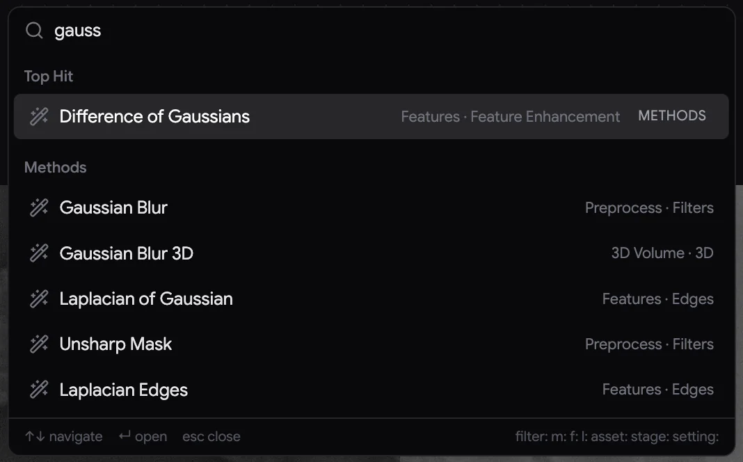
- Type a few letters. The results appear in groups: Methods, Files, Labels, Assets, Lineage, Actions and Settings. The best match is at the top, as Top Hit.
- ↑ ↓ choose a result, Enter opens it, and Esc closes Spotlight.
- Choosing a method opens it in the Workbench, ready to preview. This is the quickest way to reach a method. Methods and labels need a selected image.
- With nothing typed, Spotlight lists what you used Recently and a few Actions. They show or hide the segmentation labels or mask, open Settings, and centre on the selected image. Keys: Alt+L for labels, Alt+M for the mask.
- To search only one kind of item, start with a prefix:
m:methods,f:files,l:labels,asset:,stage:,action:,s:settings.
32.2 Agents in Studio
An AI agent connected to Samurai (Chapter 24, Working with AI agents) can also work in Studio. It can open or create projects, import data and look at images. It can try and apply operations, register and stitch, segment, measure, render and export. It uses the same processing as you, so everything it does appears as new versions in the Version panel. You can inspect, keep or delete them.
Permission. In the Connect an AI agent panel, the Studio row of Agent permissions decides if changes need your approval:
- Ask every time (default): each change shows a dialog first. Changes include applying an operation, importing, exporting and deleting. The dialog says Agent requests a project change (or …a deletion) and shows the tool and the details. Choose Allow once, Deny or Always allow. Always allow also changes this setting to Always allow. If you do not answer within 120 seconds, the request is denied.
- Always allow: changes run without asking. They are still listed in Agent activity and in the console.
Reading never needs approval, for example listing images, previews or measurements. An agent can delete only versions made by operations, never imported data. While you have an operation open in the Workbench, the agent waits. Samurai tells it: A manual operation draft is open in the Studio UI.
Data and files
This chapter describes what Samurai writes to disk and how to keep it safe. It also shows how to get images out for other software.
33.1 An experiment on disk
An experiment has two parts (Section 10.5):
- The database (
<name>-<date>-<time>.db). It holds the ROIs, tiles, cycles, settings, masks and viewport state. It is on the Samurai PC's local disk: on Windows in%LOCALAPPDATA%\Samurai3\experiments. - The data folder you chose. It holds the images and everything else the run produces.
| In the data folder | What it holds |
|---|---|
.samurai3-db |
A small link to the database. With it, you can open the experiment from its data folder. |
acquisition.zarr/<ROI>/ |
The images: one image store per ROI, with one stitched plane per cycle (Section 33.2). |
acquisition.live/<ROI>/ |
The newest cycles, not yet packed into acquisition.zarr. Part of the images: always keep it with acquisition.zarr. |
acquisition.zarr/__capture_… |
Images taken with the camera buttons of the ROI panel. |
metadata/<ROI>/ |
One small text file (.md) per tile and cycle. It holds the acquisition time, microscope settings, stage position, pixel size and any warnings (Section 16.5). |
preview/ |
SEM preview images. Their display copies are in mipmaps/. |
Autofocus/, af_diagnostics/ |
Autofocus reference images, and diagnostics for heuristic autofocus. |
overlays/ |
Imported reference images and volumes (Section 21.2). |
auto-xy/, drift/ |
The state and log of Auto XY drift, and the drift references. |
recovery/ |
Frames the image store refused, for example because the disk was full. They are saved uncompressed. The run stops at the next tile. At the next run, Samurai adds them to the store and deletes them. |
temperature-log.csv, kensho-brightness-log.csv |
Logs of the optional temperature and brightness features. |
Samurai keeps its own settings separately, in the master database ultramicrotome.db. On Windows it is in %APPDATA%\Samurai3. It holds the settings of the Settings dialog, the SEM configurations, the scripting library and the console's operation log.
33.2 The image store
Since version 3.1, Samurai writes every acquired image into an OME-Zarr image store, acquisition.zarr, instead of one TIFF file per tile. OME-Zarr is an open file format for large microscope images.
- Each ROI is one image group. Each cycle is one plane (one image), with the ROI's tiles already placed side by side.
- Each plane is also kept at 1/2, 1/4 … 1/128 size. These smaller copies form an image pyramid. With them, the viewer and Studio can show a whole experiment quickly.
- Cycles are packed in groups of 16, once a group is complete. Until then they stay in
acquisition.live. That is why both folders belong together.
The Imaging viewport reads the store. Studio streams it in place and never copies it (Section 26.1). Any software that reads the OME-Zarr 0.5 format can also read it.
Per-tile TIFF files. Some tools can read only separate image files. If you need a TIFF for every tile, switch on Settings › Advanced › Save per-tile TIFF before the run. This roughly doubles the data written. Experiments acquired before version 3.1 have per-tile TIFFs. They open as before.
33.3 Getting images out
| Need | Use |
|---|---|
| TIFF, PNG or JPEG stacks, videos, meshes, Ilastik files | Studio › Export (Section 31.3). A streamed experiment is exported as one file per ROI. |
| Aligning in Fiji / TrakEM2 | Export TIFFs from Studio. Then run Settings › Advanced › Generate TrakEM2 Imagelist on that folder. The image list needs a TIFF beside each tile's .md file. |
| Python or other OME-Zarr software | Read acquisition.zarr directly. For the newest cycles, also read acquisition.live. |
| Tile metadata | The .md files in metadata/. |
33.4 Backing up and moving experiments
- The simple way: in the Experiment panel, use Save as copy with Include images. It writes a complete copy of the database and the data to the folder you choose (Section 10.3).
- By hand: copy the data folder. Also copy the experiment's
.dbfile from%LOCALAPPDATA%\Samurai3\experiments. Do this while the experiment is not running. - Opening elsewhere: on the other PC, choose Load experiment from file. Select the
.dbfile, or the.samurai3-dblink in the data folder. The experiment remembers which SEM it was made with. If a different SEM is connected, Samurai refuses to open it.
33.5 Logs and diagnostics
- Log files. Each time Samurai starts, it writes one log file,
app-<date>T<time>.log. It is in%LOCALAPPDATA%\Samurai3\logs, or on a Mac in~/Library/Application Support/Samurai3/logs. It records every part of Samurai, with local times: the application, the backend and the user interface. At the next start, older logs move to theoldsubfolder. When you report a problem, send the log of that session. - The console in the footer shows the operator messages of this session and earlier ones (Section 6.4).
- Section telemetry. Settings › Advanced › Section Telemetry › Open viewer shows how the knife and stage moved during cutting and imaging. It shows this for each section, with image previews. Use it to track down thickness or chatter (vibration) problems. Record Full-rate Telemetry (off by default) also keeps the complete motion streams. This takes about 100 MB per hour.
Settings reference
To open Settings, click the gear at the bottom left of the footer. The dialog is one scrolling page. Click a section in the list on the left to jump to it. There is no Save button: each change is saved as you make it. A number is saved when you press Enter or leave the field. To see what a setting does, hover over beside it.
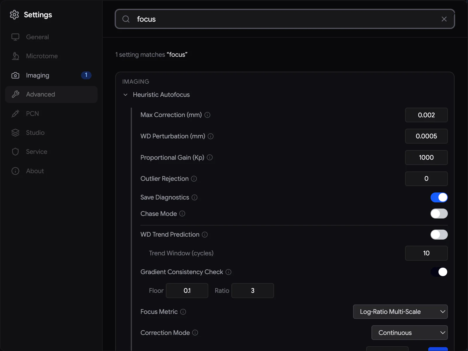
Search. Type in the search box at the top. Only the matching settings stay, each with the section it belongs to. The list on the left shows how many matches each section has. Some matches may be hidden in Service Mode or in a module that is switched off. Samurai still counts and names them, so you know where to look.
Most settings belong to Samurai on this computer. A few belong to the open experiment: Image correction and Experiment XY Offset. They need an experiment to be open.
34.1 General
| Setting | Default | What it does |
|---|---|---|
| Restore Previous Experiment | On | At start-up, reopen the experiment that was open when Samurai closed. Then go to the Imaging tab. |
| Scroll Wheel | Automatic | What a plain scroll does in the viewports. Automatic: a scroll pans, and pinch or Ctrl/⌘ + wheel zooms. Zoom: a scroll zooms. |
| Time Travel Click Sound | On | A soft click for each cycle step as you move through Time Travel. |
| Colors | — | The colour, background tint and text effect of the information overlays in the viewport. |
34.2 Microtome
| Setting | Default | What it does |
|---|---|---|
| Connection | USB | USB finds the controller on the serial ports. TCP connects to a simulator or a controller on the network, by IP address and port. A change applies at the next connection. |
| Auto-connect Microtome | On | Connect when Samurai starts. |
| Warn on Z Re-sync | On | At Start, if the stage Z differs from the saved Z of the next cycle, ask what to do. If off, update the saved Z without asking (Section 15.10). |
| Knife Fast Speed | 5 mm/s | The knife speed when retracting and outside the cutting window (the part of the stroke over the block). |
| Knife Jog Speed | 500 DAC/s | The knife speed with the jog buttons. |
| Knife Jog Keyboard Shortcuts (A/D) | Off | Hold A or D to jog the knife. |
| Drag Speed, Shift-Drag Precision | Normal | How the knife follows the mouse when you drag it (Section 9.4). |
| Motor Stop Precision | 1 count | How close the motor must get to its target before it stops. If the motor moves back and forth around its target, raise this value. |
| Controller Firmware | — | Update the firmware of the microtome controller (Section 5.4). |
34.3 Imaging
| Setting | Default | What it does |
|---|---|---|
| Beam Off on Complete | Off | Switch the beam off when a run completes. This does not happen when you stop a run. |
| Image correction | Original | For the open experiment. Corrects uneven brightness and contrast in the display with flat fields (correction maps). The recorded images do not change. Generate from experiment… computes the fields from acquired cycles (Section 16.2). |
| Image Quality Validation | — | Min Standard Deviation: a nearly flat tile counts as a failed tile (Section 16.3). Default 3, switched off. Max Clipping Allowed: warn once per cycle if a tile has too many black or white pixels. Default 5 %, switched on. Rebin before counting (2×2) averages pixels in blocks first, so single noisy pixels are ignored. Max Sequential Failed Tiles Allowed: how many failed tiles in a row are allowed before the run stops. Default 0. |
| Debris Detection | — | Kernel size, threshold and sweep settings (Section 18.4). |
| Heuristic Autofocus | — | Tuning for heuristic autofocus and autostigmation (Section 17.6). You choose the method itself in the Autofocus panel. |
34.4 Advanced
| Setting | Default | What it does |
|---|---|---|
| Experiment XY Offset | 0, 0 | The total X/Y offset added to every stage move in the open experiment (Section 19.1). |
| ROI Lock Priority | per SEM | Which ROI settings change first when locks force a change (Section 13.3). |
| Temperature Logging, Temperature Source URL | Off | Record the room temperature with each image (Section 16.5). |
| Image Drift Warning | 1000 nm | Warn when the bright reference tile has moved this far since the start. It only measures; it corrects nothing. |
| Save per-tile TIFF | Off | Also write a TIFF for every tile (Section 33.2). |
| SEM / Microtome / PCN Failed Action Retries | 3 | How many times a failed command is tried again before the run pauses. The SEM and microtome values apply after a restart. |
| Max Tiles Ahead of the Image Store | 1 | How many images may wait in memory for the store before the next one is taken. A larger value copes better with a slow disk. But if the power fails, more images are lost. |
| Record Full-rate Telemetry | Off | Keep the complete motion records of the knife, needle and stage. This takes about 100 MB per hour. |
| Section Telemetry | — | Open viewer shows the recorded motion of each section, during cutting and imaging (Section 33.5). |
| Stage Moving / Idle Poll Interval | 100 ms | How often Samurai reads the stage position while the stage moves / while it is still. |
| Viewport Tracking Smoothing | On | The viewport glides to a new stage position instead of jumping. |
| Emergency Recovery | — | Last-resort fixes for a stuck system. See the warning below. |
| Generate TrakEM2 Imagelist, Flip X / Flip Y | — | Make an image list for Fiji/TrakEM2 (Section 33.3). |
34.5 Kensho BSED, PCN and Studio
These sections appear only when their module is enabled:
- Kensho BSED: the detector's motor settings, control signals, the brightness and contrast ranges, and a serial terminal.
- PCN: connection, indexing, Z lift per XY move, knife safety, the needle's appearance, the calibration and the Retracted position (Chapter 20, The PCN needle).
- Studio: Lineage Cleanup and Storage Warning. They are for projects made by older versions of Studio. In current projects, you manage disk space with Prune in the Version panel (Section 28.4).
34.6 Service
Service Mode unlocks settings meant for service engineers. It needs the service password: ask ConnectomX or your administrator. Service Mode locks again at every restart, unless Disable Service Mode on App Restart is switched off.
| Group | Contents |
|---|---|
| Enabled Modules | Switch on the optional modules: Kensho BSED, Studio, EDS (Oxford AZtec) and PCN. |
| Stage and memory | Stage Position Tolerance: how precisely the stage must arrive (default 10 µm). Viewer Memory (% of RAM): the share of RAM the image viewer may use (default 25 %). |
| PCN | Open PCN service panel (Section 20.11). Tuning for PCN tracking. Knife safety DAC (default 4900). |
| Developer Tools | Logging level, activity indicators, performance overlay, diagnostics recorders and memory caps. Also the microtome's DUMMY MODE, for tests without a microtome. |
| Visual Tracking, Display & UI, Histogram, Database | Fine-tuning of the stage marker, viewport tracking, the display and database performance. |
About shows the version of Samurai.
Keyboard and mouse reference
On macOS, use ⌘ where this chapter says Ctrl/⌘. Shortcuts do nothing while you are typing in a field.
35.1 Everywhere
| Keys | Action |
|---|---|
| Esc | Stop a moving PCN needle, if the PCN is connected. Cancel the current mouse action or dialog. |
| Ctrl/⌘+Z | Undo, in the tab you are in. |
| Ctrl/⌘+Shift+Z or Ctrl/⌘+Y | Redo. |
35.2 Imaging viewport
| Keys / mouse | Action |
|---|---|
| Scroll | Pan. If Scroll Wheel is set to Zoom, zoom instead. Shift + scroll pans sideways. |
| Pinch, Ctrl/⌘ + scroll | Zoom, 15 % per notch. With Shift, 3 %. |
| Space + drag, middle-button drag | Pan. |
| V / H / D | Select / Hand / Draw ROI tool. |
| 0 | Zoom to each ROI in turn, then all ROIs, then the SEM position. |
| 1–4 | Show image pixels at 1:1 … 4:1. |
| Numpad . | Go to the SEM stage position. |
| Ctrl/⌘ + click, Alt + click | Add a tile to the selection / remove it. |
| Drag on empty space | Select tiles with a box. |
| Shift + drag | Select tiles with a lasso (freehand). |
| Shift + click, click… (Enter to close) | Select tiles with a polygon. |
| I | Invert the tile selection inside its ROI. |
| ↑ ↓ ← → | Move through the ROI list. Expand or collapse an ROI. |
| Drag a selected ROI + Shift / T / G | Move it along one axis / by whole tiles / onto the grid. |
| ' | Selection Scope: limit clicks to one ROI or mask. Press again to clear. |
| Right-click | Context menu: Drive SEM Stage Here, Zoom 1:1, Selection Scope… |
35.3 Masks
| Keys / mouse | Action |
|---|---|
| G / R / S | Move / rotate / scale the selected mask or volume. |
| X Y Z | Limit to one axis. Press again for the item's own axis. |
| Numbers, ., - | Type an exact amount while you move, rotate or scale. |
| Enter or left-click / Esc or right-click | Confirm / cancel the change. |
| Shift (held) | Ten times finer. |
| Shift + right-drag | Place the 3D cursor. X / Y keep it on one line. |
| While tracing: Enter / Backspace / Esc | Close the shape / remove the last point / discard the shape. |
35.4 Time Travel, Approach and run
| Keys / mouse | Action |
|---|---|
| Scroll over Time Travel | Step one cycle (up = later). With Ctrl/⌘, ten cycles. |
| Home / End on Time Travel | Go to the first / last cycle. |
| A / D (held) | Jog the knife, if switched on in Settings › Microtome. |
| Shift + drag the knife diamond | Move the knife in fine steps. |
| Ctrl/⌘+Shift+K | Show the knife's exact position above the track, in the Approach tab. |
35.5 Studio
| Keys | Action |
|---|---|
| Ctrl/⌘+K | Spotlight search. |
| V H C | Select, Hand, Crop (in edit mode). |
| L R O P | Line, Rectangle, Ellipse, Point. |
| B / E, [ / ] | Pixel Classifier: Brush / Erase, and a smaller / larger brush. |
| 0–9 | Choose a classifier class. With the Point tool, choose a counting class 1–9. |
| F or numpad 0 | Fit the frame in the view. |
| Numpad 1–4, numpad . | Zoom to 100 %–400 % / centre on the selected image. |
| G / K | Show or hide the grid / the scale bar. |
| M (held) | Show the loupe (a magnifier). |
| Shift+M | Measure the selected image. |
| Alt+L / Alt+M | Show or hide the classifier labels / mask. |
| Arrow keys | Move the selected annotations a little. With Ctrl/⌘, ×10. With Shift, ×0.1. |
| Ctrl/⌘+C / V / D | Copy / paste / duplicate annotations. |
| Delete | Delete the selected annotations. In the Explorer, delete the selected items. |
| Esc | Discard the open operation. Clear the Explorer selection. |
| Ctrl/⌘+Z | Undo. If there is nothing left to undo, go to the parent version. |
The Explorer has its own shortcuts, for example to select, filter, duplicate, split and move frames: see Section 26.4.
Troubleshooting
When Samurai refuses an action or stops, it tells you why. Read the message: the title says what happened, and the text below it says what to do. For the full story, look in the console in the footer. This chapter lists the common situations. When you ask for help, send the log file of the session (Section 33.5).
36.1 Connections
| Symptom | What to do |
|---|---|
| The SEM badge stays red. | Check that the Universal SEM Bridge is running on the microscope PC and shows the microscope as connected. Then check that the IP address and port in Samurai's SEM connection settings match the bridge (Section 7.2). |
| The microtome badge is red, or its cable indicator turns red. | Check the controller's power and USB cable. Then click the badge to reconnect. After a cable loss, the stage may have drifted. Before cutting, lower it by more than 2 µm and approach again (Section 7.4). |
| PCN Disconnected. | Check the PCN controller and its USB cable, then click the badge. When the controller answers, the badge turns green again by itself. |
| A connection works but values look wrong. | A green badge only proves that Samurai can talk to the equipment. Check the beam, detector and chamber on the microscope itself. |
36.2 Starting a run
If the Start button is unavailable, its tooltip says why. For example: Generate cycles first, Microtome not connected or Connected SEM does not match this experiment. When you press Start, these are the common refusals:
| Message | What to do |
|---|---|
| Cannot start acquisition: SEM is not connected | Connect the SEM. |
| …connected SEM does not match this experiment | Connect the SEM the experiment was made with. |
| …stage is at an elevated imaging position | The stage is still raised by Imaging Addition (the small lift for imaging). Lower it with the arrow in the warning, then start (Section 15.2). |
| …imaging addition exceeds the stage limit | Reduce the Imaging Addition, or switch it off for this run. |
| Cannot start imaging: no enabled tiles found | Enable at least one ROI with tiles. |
| …reference-frame configuration is incomplete | Mark the dark and the bright reference on two different tiles, or mark neither (Section 16.3). |
| Very Long Tile Acquisition | A tile will take more than 5 minutes. Check the dwell time and its units. Then choose Start anyway or Cancel. |
| Microtome Z Position Changed / Resume Z Mismatch | The stage is not at the height the next cycle expects. To update the saved heights from the stage, continue. Or cancel, and move the stage (Section 15.10). |
| Microtome Z Position at Zero | The stage reads exactly 0 µm. This is unusual after an approach. Continue only if you are sure the block is at the cutting plane. |
| The previous cut has no completion record | Samurai cannot confirm the last cut. Check the block face and the Z position. If the cut happened, click Clear cut record and start again. |
| PCN axes not indexed, Needle not engaged for Tracking, Needle could not be parked before the run, Knife protection stopped imaging | See Section 20.10. |
36.3 During a run
When a run pauses, it shows Stopped, and the console gives the reason (Imaging paused during cycle …). Fix the cause and press Start to resume. The cycle continues from where it stopped, and unfinished tiles are imaged again.
| Pause or warning | What to do |
|---|---|
| Tile A2 of ROI_1 (cycle 6) could not be captured | Samurai tries the tile once more at the end of the cycle. If many tiles fail in a row, the run pauses (Max Sequential Failed Tiles Allowed). Check the SEM and the bridge. |
| Blank tile: standard deviation … is below the minimum of … | Min Standard Deviation rejected a nearly flat tile. Check that the beam is on and the column valve is open. Check that the detector is inserted and selected. If the tiles really are flat, for example empty resin, lower the value or switch the check off (Section 16.3). |
| SEM unavailable… | The microscope cannot image, for example because the beam is off, it is venting, or an interlock is active. Fix this on the microscope, then resume. |
| Stage Z is … but cycle … expects … | The stage was moved, or the sample height changed. Run Z Resync: press Start and accept. Or move Z back. |
| Stage Z stayed … from the … plane / The Katana did not hold the … plane | The microtome could not reach or hold its height. Check the controller's fault light and cable, and the sample mounting. Then resume. |
| The disk is full | Free space on the data disk, then resume. |
| Image store failed | A frame could not be written, so Samurai saved it in recovery/ (Section 33.1). Check the disk, then resume. |
| Clipping warning | A tile has too many black or white pixels. Adjust brightness and contrast on the SEM. The run continues. |
| Debris sweeps run on clean tiles, or debris is missed | Adjust the debris threshold (Section 18.5). |
| Focus drifts, or autofocus corrections look wrong | See Section 17.7. |
| Images slowly shift between cycles | Use XY Offset or Auto XY drift (Chapter 19, Correcting drift and brightness). |
| The needle blocks a tile (Fixed or Tracking) | Move the needle back to Engaged, or set the PCN to Off (Section 20.3). |
36.4 Approach
For thick or missing first sections, a knife that does not move, or a stage that does not rise, see Section 9.9.
36.5 Images and display
| Symptom | What to do |
|---|---|
| Images too dark or washed out in the viewport | Use Auto in the histogram, or check the SEM brightness and contrast (Section 16.1). |
| Tiles of one ROI differ in brightness | For the display, use Image correction with a flat field (Section 16.2). For the images themselves, use Studio's Level tile brightness or the background methods. |
| The viewport is slow | Close other programs and show fewer overlays. Make sure the data is on a local disk. |
| A tile image looks cut or misplaced | While the cycle is still running, right-click the tile and choose Re-acquire in This Cycle. |
36.6 Studio
| Message or symptom | What to do |
|---|---|
| Select images first… | In the Explorer, select the stack, frames or images to process (Targets: what the next operation changes). |
| Finish or cancel … first. | An operation is still open. Apply it with ✓, or discard it with ✕ or Esc. |
| …Consolidate Stack first | The frames come from separate files, or were reordered. Right-click the stack and choose Consolidate Stack. |
| …stitch mosaic tiles first | Stitch the tiles with Tile Alignment (Section 29.1). |
| The pixel classifier needs the images stored inside the project | First apply any operation to the streamed stack. Then train on the result (Section 30.1). |
| … may be stuck | Studio has seen no progress for a while. Wait, or choose Cancel or Stop waiting (Section 28.6). |
| Volume too large for … | Select a smaller region, a shorter range of frames, or a higher bin. |
| A new stack does not show in the Explorer | The Explorer shows only the version you are on, the selected versions and the kept ones. Click the stack in the Version panel, or keep it with the eye (Chapter 28, Processing and versions). |
| Disk filling up | Delete versions you no longer need, then use Prune (Section 28.4). |
| Stream unavailable… | The experiment folder has moved, or Studio cannot reach it. Reconnect the drive, or move the folder back. |
36.7 When nothing else helps
- Write down what you did and what the message said. A screenshot helps.
- Find the log file of the session (Section 33.5).
- Contact ConnectomX support with both.
Do not use the Emergency Recovery buttons in Settings unless support asks you to (Section 34.4).
Good practice
This chapter collects advice from many long runs.
37.1 Before the first cut
- Prepare the block well. Trim the block face small and neat, with the tissue near the surface. A block like this cuts more evenly. It also suffers less from charging, a build-up of electrons that spoils the image (Chapter 4, Sample preparation).
- Look after the knife. A clean, undamaged edge matters more than anything else for section quality. Clean it before each experiment, and check it under the optical camera (Section 5.1).
- Approach slowly near the surface. When the knife starts to touch, use thin steps. Watch the camera for the first full sections (Chapter 9, The approach).
- Check the chamber clearance before you move the stage or the SEM stage a long way (Section 3.2).
37.2 Planning the imaging
- Choose the pixel size for the smallest structure you need to see. That structure should be at least two to three pixels wide. Finer pixels cost more time, dose and disk space, in proportion to their number. Dose is the number of electrons per area.
- Balance dose against charging. A longer dwell or a higher current gives cleaner images. But it also gives more charging and beam damage. The dose calculator in Section 11.5 helps. If charging is a problem, lower the dose, use the PCN needle, or both.
- Use about 10 % overlap between tiles if you will stitch them.
- Estimate time and disk space before you start. The dose calculator in Section 11.5 shows the time for one tile. The tile calculator in Section 12.4 shows how many tiles you get. The disk calculator in Section 33.2 shows the disk space.
- Take previews and test a few cycles with the real settings. Do this before you commit to days of imaging.
- Lock what matters. When you have decided on ROI parameters, lock them. Then later edits cannot change them by accident (Chapter 13, Locking ROI geometry).
37.3 Setting up a reliable run
- Autofocus: mark one or two tiles with clear, fine structure. Choose tiles that are imaged early in the cycle (Section 17.2).
- Debris detection: choose an ROI with stable structure. Tune the threshold on the first cycles (Chapter 18, Debris detection).
- Drift: start Auto XY drift in Measure only. When the measurements look right, apply corrections (Section 19.2).
- Masks and gating: skip tiles outside the tissue. This is often a large saving on long runs. Before you Sync, check the red and green preview at several cycles (Section 21.7).
- PCN: calibrate after every re-indexing. Draw the gas footprint. Never disable knife protection while a needle is fitted (Chapter 20, The PCN needle).
- Scripts: test every action with Test. Switch on only the sequences you need (Chapter 23, Scripting).
37.4 During the run
- Check the console from time to time for warnings. Look back through the last cycles with Time Travel.
- Let an agent watch long unattended runs. Give it Manual permission: then it can stop the run, but it asks before anything else (Section 24.4).
- Change settings for the future, not the past: a change you make while viewing a future cycle applies from that cycle on (Section 14.3).
- Stop cleanly. When you need to step in, use Stop at end of this cycle. It leaves the block uncut and ready to resume (Section 15.8).
- Avoid disturbing the instrument. Vibration, temperature changes and opening the chamber all show up in the images.
37.5 Looking after the data
- Back up both parts of every experiment: the data folder and the database. Or use Save as copy (Section 33.4).
- Keep enough free disk space for the whole run, on a local disk.
- Use one Studio project per experiment. Stream the experiment (open it in place) instead of importing copies.
- In Studio, try on a few frames first, then apply to the whole stack. Delete versions you do not need, and use Prune now and then (Section 28.4).
- Keep the log of any session in which something went wrong (Section 33.5).
Glossary
| Term | Meaning |
|---|---|
| Acquisition | An automatic run of cycles: image, then cut, again and again. |
| Agent (AI agent) | An outside AI program connected to Samurai through MCP. It can watch or operate Samurai, within the permissions you set (Chapter 24, Working with AI agents). |
| Approach | Bringing the knife and the block surface together, until the first full sections are cut (Chapter 9, The approach). |
| Autofocus | Automatic correction of the working distance during a run. The related autostigmation corrects astigmatism (Chapter 17, Autofocus and autostigmation). |
| Bin | Averaging blocks of pixels (or voxels) into one. This makes images smaller and faster to work with. |
| Bridge (Universal SEM Bridge) | The program on the microscope PC that connects Samurai to the SEM (Section 7.1). |
| Carried frame | In Studio, a frame that a version did not process. It is shown from the parent version, without a copy. |
| Checked out | In Studio, the version you are working on. The viewport shows it, and the next operation reads it. |
| Console | The message log in the footer (Section 6.4). |
| Cutting window | The part of the knife's travel over the block. The knife crosses it at cutting speed. |
| Cycle | One section: image the ROIs, then cut. Cycles are numbered from 1. |
| Delta Z | In Studio, the distance between frames (the section thickness). |
| Disabled tile | A tile that is skipped in runs and captures. You set it by hand, or tile gating sets it. |
| Dose | The number of electrons that hit the sample per unit area (e⁻/nm²). |
| Drawn mask | A mask made of shapes you trace at chosen cycles (Section 21.3). |
| Dwell time | How long the beam stays on each pixel. |
| Dwell Ease-In | Starting a run with shorter dwell times, which increase over the first cycles. |
| Engaged / Retracted | Engaged is the PCN needle's imaging position. Retracted is its safe position away from the knife (Section 20.4). |
| Experiment | Everything about one run: ROIs, cycles, settings and images (Chapter 10, Experiments). |
| Explorer | Studio's list of stacks, frames and images (Section 26.4). |
| Field of view (FOV) | The width and height of the area one image covers. |
| Flat field | A correction for uneven brightness across an image. |
| Frame | In Studio, one position in a stack, usually one section. |
| Gas footprint | The area where the PCN needle's gas lands (Section 20.7). |
| Imaging Addition | Raising the stage a little for imaging, then lowering it again for cutting (Section 15.2). |
| Index (PCN) | Moving the PCN axes through their travel to find their reference points (Section 20.9). |
| Keyframe | A shape of a drawn mask at one cycle. Between keyframes, the mask changes smoothly from one shape to the next. |
| Live cycle | The cycle the run is on, or will start with. Earlier cycles are history. |
| Lock | ROI parameter locks keep chosen values fixed (Chapter 13, Locking ROI geometry). A locked ROI or mask cannot be edited. |
| MCP | Model Context Protocol: the way AI agents talk to Samurai. |
| Mosaic | Several overlapping tiles that together cover an area. |
| OME-Zarr | The open file format of Samurai's image store, acquisition.zarr (Section 33.2). |
| Overlap | How much neighbouring tiles cover the same area. Stitching needs it. |
| PCN | The optional needle that blows gas onto the imaged area. Three piezo motors move it (Chapter 20, The PCN needle). |
| Pixel Classifier | Studio's segmentation tool. It learns from examples you paint (Section 30.1). |
| Pixel size | The width of the sample area that one pixel shows. |
| Preview | A single SEM image taken outside a run, to check the settings (Section 11.2). |
| Prune | Freeing disk space that no Studio version uses (Section 28.4). |
| Reference volume | An imported 3D image, for example a microCT scan, aligned to the experiment (Section 21.2). |
| ROI | Region of interest: an area to image, divided into tiles (Chapter 12, Regions of interest and tiles). |
| Section | The thin layer removed by one cut. Samurai images the block face that the cut reveals. |
| Selection Scope | Limiting viewport clicks to one ROI or mask. The key is ' (Section 8.5). |
| Stack | In Studio, an ordered series of frames. |
| Stream | Bringing an experiment into a Studio project live, without copying it (Section 26.1). |
| Sweep | A knife stroke that does not advance the stage, for example to clear debris. |
| Sync (gating) | Writing the tile-gating decision to the tiles (Sync: apply the decision). |
| Targets | What the next Studio operation will change. They come from the Explorer selection (Targets: what the next operation changes). |
| Tile | One image position in an ROI. |
| Tile gating | Skipping the tiles that a mask does not cover, cycle by cycle (Section 21.7). |
| Time Travel | Viewing and editing earlier or later cycles (Section 14.2). |
| Tracking (PCN) | The PCN mode in which the needle follows the SEM stage (Section 20.3). |
| Version | In Studio, every stack is a version. Versions have codes: A01, A02, B03… (Chapter 28, Processing and versions). |
| Viewport | The central image area of the Imaging tab and of Studio. |
| Z lift | How far the PCN needle rises before every sideways move (Section 20.4). |